background image


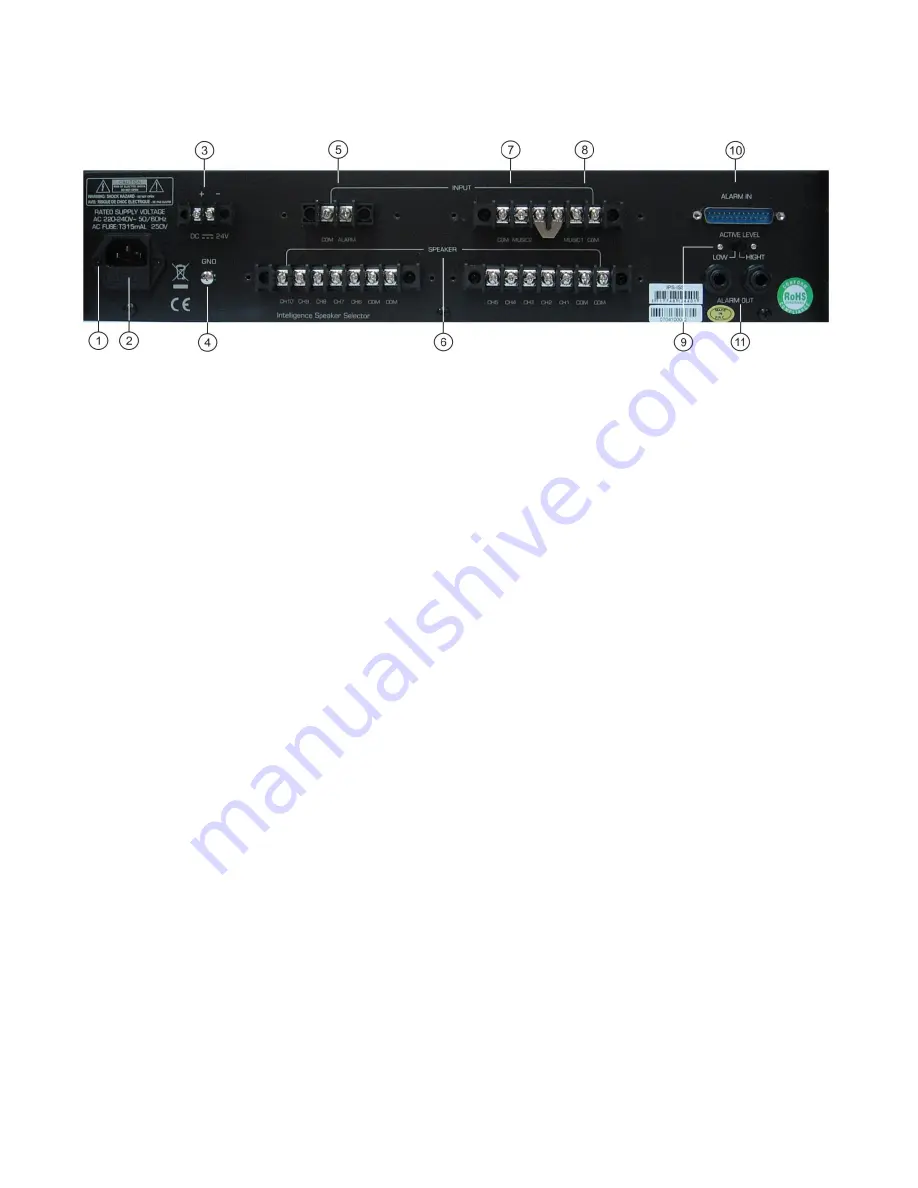
Back panel 


            Fig. 2 


1. 

AC Inlet. 

      This connector is meant for the connection of the supplied main cord. Connect one end of the power  
      cord to the connector, the other end to the mains, then turn on the power switch (1) to operate  
      the unit. 

Note: 

Please make sure that the supply voltage matches the operation voltage before  

      connecting the unit to mains.


  2.

 Fuse Holder. 

      Replace only with a fuse of same specification.


  3.


DC 24V Input. 


Used to connect an external back up power supply of 24Vdc (e.g. Battery). 

  4.


GND Screw.


      This screw offers a separate ground connection. Can be useful in case of grounding problems. 


5. Input Alarm. 


This input is used to connect an (audio) alarm signal. 

  6.

 Speaker. 


The unit select up to 10 speaker(group)s. 

  7. Input Music 2. 

      If the metal bridge is inserted, the unit functions as a one in 10 out system. If the bridge is removed, the         
      unit functions as a two in five out system. In a two in five out system, you have to connect both Input 1  
      and input 2. If the system is used as a one in ten out system, you can use either input 1 or input 2. 

  8.


Input Music 1. 

      If the metal bridge is inserted, the unit functions as a one in 10 out system. If the bridge is removed, the         
      unit functions as a two in five out system. In a two in five out system, you have to connect both Input 1  
      and input 2. If the system is used as a one in ten out system, you can use either input 1 or input 2. 

  9.

 Active Level. 

      High-level signals are valid when the switch is set to HIGH position. In LOW position, low-level signals  
      are valid.  

11. Alarm In. 
      

If an alarm signal is received at any of the 10 alarm inputs,  

the corresponding CH will go to “Alarm- 

      mode”.


The corresponding LED will blink and alarm out will be activated. If the incoming alarm is reset.  

      Music will continue automatically on the selected channels. 

For pin layout of the 25-pole connector see  

      page 7. 

10. Alarm Out

      If any of the 10 channels is in alarm mode, the Alarm out (N.O.) contact will be closed.   


Summary of Contents for IPS-ISS

Page 1: ...IPS ISS ORDERCODE D6510...

Page 2: ...d You can rely on DAP Audio for more excellent audio products We design and manufacture professional audio equipment for the entertainment industry New products are being launched regularly We work ha...

Page 3: ...afety instructions Operating Determinations Connecting to the mains Description Features Overview Front panel Overview Back panel Operation Connecting the device Alarm in connector Emergency alarm Con...

Page 4: ...connect this system to a dimmer pack Do not switch the system on and off in short intervals as this would reduce the system s life Do not open the device and do not modify the device Do not open this...

Page 5: ...l components connected to the device have sufficient power ratings Otherwise distortion will be generated because the components are operated at their limits Avoid ground loops Always be sure to conne...

Page 6: ...ill light If an alarm comes in CH1 CH10 the corresponding Channel will go in Alarm mode The corresponding LED will blink and alarm out will be activated If the incoming alarm is reset Music will conti...

Page 7: ...in five out system In a two in five out system you have to connect both Input 1 and input 2 If the system is used as a one in ten out system you can use either input 1 or input 2 8 Input Music 1 If t...

Page 8: ...needs 2U rackspace Connect all cables Connecting the device Below an example of a possible setup NOTE Always turn off and disconnect the devices from mains voltage before making any connections Fig 3...

Page 9: ...OUT to REMOTE IN of an emergency alarm generator As soon as the Alarm Matrix receives an alarm signal the ALARM OUT will send an alarm signal to activate the emergency alarm Fig 5 Output connection U...

Page 10: ...a slot in the fuse cover Gently pry up the fuse cover The fuse will come out 3 Remove the broken fuse If brown or unclear it is burned out 4 Insert the replacement fuse into the holder where the old f...

Page 11: ...way background music 1 way alarm Number of output channels Two 5 way or One 10 way outputs Alarm Out When broadcasting music it s short circuit when broadcasting alarm it s open circuited Dimensions W...

Page 12: ...2007 DapAudio...

Reviews: