5
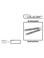
Fig. 3
11)
Antenna B
12)
Unbalanced 1/4” jack plug
13)
Balanced XLR Connector
14)
Mixed Channels Audio Output Connector: Unbalanced 1/4” jack plug connector mixes both
channels into a single output.
15)
Power Input Connector 12V 600mA
16)
Balanced XLR Connector
17)
Unbalanced 1/4” jack plug
18)
Antenna A
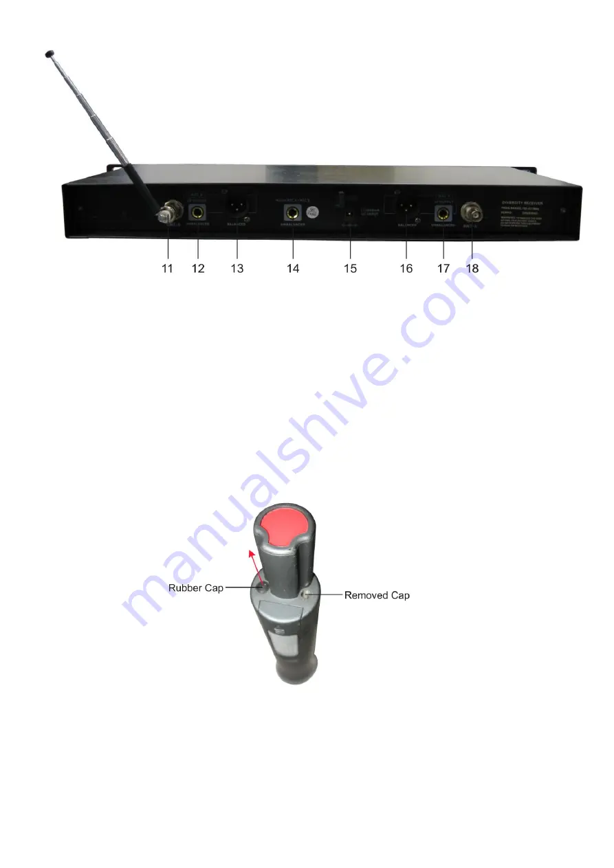
Installation
Remove all packing materials from the Com-52. Check that all foam and plastic padding is removed. Put
the 2 antennas into socket A and B at the backside in a vertical angle. Remove the rubber protection
caps at the underside of the microphones that covers the recharge inputs (See Fig 4).
Fig. 4
When connecting the powersupplies, assure yourself that the right supplies are connected to the right
devices. Look at the red/green sticker at the bottom of the microphone.
Always disconnect from electric mains power supply before cleaning or servicing.
Damages caused by non-observance are not subject to warranty.
Summary of Contents for COM-52
Page 1: ...COM 52 v3 ORDERCODE D141279 ORDERCODE D141282...
Page 19: ...2010 Dap Audio...