31
www.Daniel.com
USER MANUAL
4.3
Torque values (flanges)
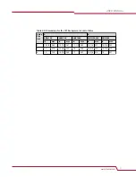
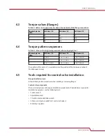
Table 4-1: Reference torque values for Daniel Control Valve (ft-lb) flange connections
Nominal pipe size
(NPS)
ANSI class 150
ANSI class 300
ANSI class 600
2
90
90
90
3
90
160
160
4
90
160
250
4.4
Torque pattern sequences
Table 4-2: Cross-pattern tightening sequence when using single tool
Nominal pipe size
(NPS)
ANSI class 150
ANSI class 300
ANSI class 600
2
1-3-2-4
1-5-3-7 2-6-4-8
1-5-3-7 2-6-4-8
3
1-3-2-4
1-5-3-7 2-6-4-8
1-5-3-7 2-6-4-8
4
1-5-3-7 2-6-4-8
1-5-3-7 2-6-4-8
1-5-3-7 2-6-4-8
The position of the number 1 screw determines the position of the clockwise rotation of
the subsequent screws.
4.5
Tools required for control valve installation
Flange installation tools
Follow all best practice procedures when installing or removing flanges.
Control valve components
The control valve does not have pre-installation requirements. If installation is required for
maintenance purposes, use the following tools:
•
Socket wrench
•
Adjustable wrench
•
T-handle or extended Allen wrench
•
Arbor press (may be needed for 4- and 6-inch valves)
•
Retaining ring pliers
Installation prerequisites
User manual
August 2019
DAN-20064957
38
707 Spring Loaded Back Pressure Valve


