background image


6.2.7 Warning 71, PTC 1 Safe Stop

STO has been activated from VLT

®

 PTC Thermistor Card MCB 112 (motor too warm). Normal operation can be resumed when:

The MCB 112 applies 24 V DC to terminal 37 again (when the motor temperature reaches an acceptable level), and
The digital input from the MCB 112 is deactivated.

W A R N I N G

AUTOMATIC RESTART

When the conditions of the PTC circuit and/or emergency stop circuit have returned to normal, the motor restarts automatically.

6.2.8 Alarm 72, Dangerous Failure

STO with trip lock. If the combination of STO commands is unexpected, the dangerous failure-alarm is issued. This situation occurs if
the VLT

®

 PTC Thermistor Card MCB 112 enables X44/10 without STO being enabled. Furthermore, if the MCB 112 is the only device

using STO (specified in 

[4] PTC 1 alarm

 or 

[5] PTC 1 warning

 in 

parameter 5-19 Terminal 37 Safe Stop

), an unexpected combination

activates the STO without activating the X44/10. 

Table 7

 summarizes the unexpected combinations that trigger this alarm.

N O T I C E

If X44/10 is activated in 

[2] Safe stop alarm

 or 

[3] Safe stop warning

, this signal is ignored. However, the MCB 112 is still able to

activate STO.

N O T I C E

For correct and safe use of the STO function, follow the related information and instructions in the VLT

®

 Frequency Converter -

Safe Torque Off Operating Guide.

Example

[5] PTC 1 Warning

 is selected in 

parameter 5-19 Terminal 37 Safe Stop

, and X44/10 is not activated, but STO is. This is an unexpected

selection. 

[5] PTC 1 Warning

 in 

parameter 5-19 Terminal 37 Safe Stop

 specifies that STO is only triggered from MCB 112.

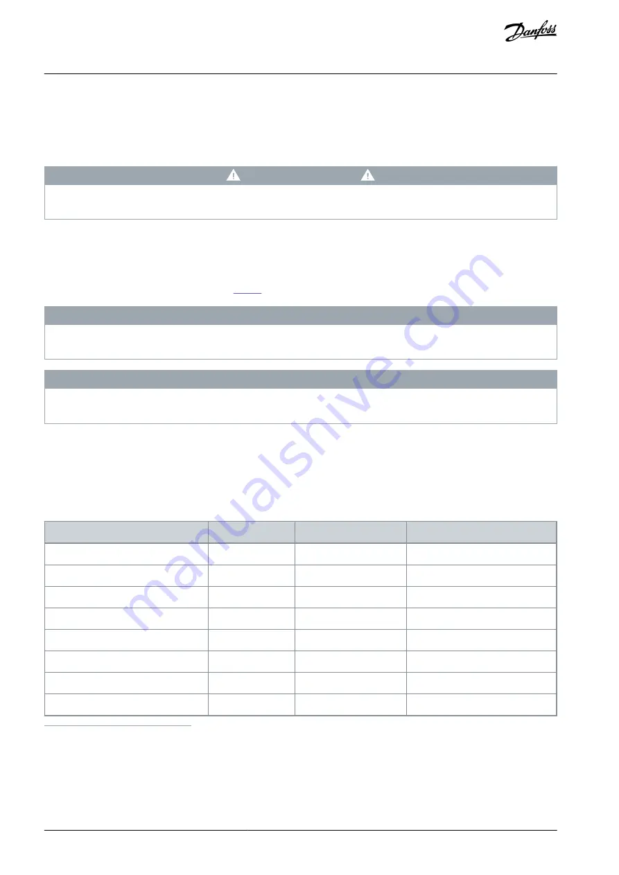
6.2.9 Unexpected Combinations

Table 7: Unexpected Combinations Triggering Alarm 72 Dangerous Failure

Function

Number

X44/10 (DI)

STO terminal 37

PTC 1 Alarm

[4]

+

(1)

-

(2)

-

+

PTC 1 Warning

[5]

+

-

-

+

PTC 1 & Relay A

[6]

+

-

PTC 1 & Relay W

[7]

+

-

PTC 1 & Relay A/W

[8]

+

-

PTC 1 & Relay W/A

[9]

+

-

1

+ = Activated

2

- = Not activated

AQ267038105120en-000101 / 130R0104

28 | Danfoss A/S © 2022.08

Maintenance and Troubleshooting

VLT® PTC Thermistor Card MCB 112

Operating Guide

Summary of Contents for VLT PTC Thermistor Card MCB 112

Page 1: ...Operating Guide VLT PTC Thermistor Card MCB 112 VLT HVAC Drive FC 102 VLT AQUA Drive FC 202 VLT Automation Drive FC 302 vlt drives danfoss com...

Page 2: ......

Page 3: ...Disconnection Principle Diagram 8 Motor Requirements 9 Motor Limits and Rules 9 Additional Motor Requirements 9 Approvals and Certifications 9 Abbreviations and Conventions 9 Abbreviations 9 Conventio...

Page 4: ...ncy 21 Maximum Motor Frequency 22 Minimum Switching Frequency 22 Disable Protection Mode 22 Safe Torque Off Functionality 22 Functions Alarms and Warnings 23 Application Examples 24 Setting up the Opt...

Page 5: ...X44 2 29 Safe Stop Terminal 37 X44 12 29 Logic out X44 10 29 Ambient Conditions 29 Environment 29 Testing Conditions 29 Other Specifications 30 Safety Characteristics of the Built in MCB 112 30 AQ267...

Page 6: ...of this guide is English Table 1 Version History Version Remarks MG33V302 Editorial changes Now covering the complete system AQ267038105120 version 0101 Update for compliance to ATEX directive 2014 34...

Page 7: ...NGER Zone 0 and Zone 20 are not applicable to electrical motors Using electrical motors in those zones can cause explosions Only use elecrical motors in Zone 1 21 Zone 2 22 1 5 3 Thermal Motor Protect...

Page 8: ...g function switches off the 24 V DC directly at terminal 37 on the drive The PNP logic output terminal X44 10 signals the status in case of failure The MCB 112 works according to the closed circuit pr...

Page 9: ...in Zone 1 21 or 2 22 according to motor approval The drive must always be installed outside of the hazardous zone Only operate explosion protected 3 phase motors with drives if the motors are built t...

Page 10: ...on or a subsystem related to all failures SIL EN IEC 61508 EN IEC 62061 Safety integrity level STO EN IEC 61800 5 2 Safe Torque Off SRECS EN IEC 62061 Safety related electrical control system 1 7 2 Co...

Page 11: ...rds applicable to the specific application 2 3 Responsibilities of Users of Safety related Power Drive Systems PDS SR Users of safety related Power Drive Systems PDS SR are responsible for Carry out a...

Page 12: ...ts as well as the European Standard EN 60079 14 Explosive atmospheres Part 14 Electrical installations design selection and erection Only qualified personnel is allowed to install connect and commissi...

Page 13: ...he type label of the drive and also specified in the Discharge time tables in the FC 102 202 302 Operating Guides Use a measuring device to make sure that there is no voltage before opening the drive...

Page 14: ...r wires with a resistance 20 causes the safe function not to work To ensure a properly working safe function only use sensor circuit wires with a resistance 20 Wire cross section mm2 AWG Wire length m...

Page 15: ...or the VLT PTC Thermistor Card MCB 112 as follows Procedure Select the appropriate sensor wires Route the sensor wires Remove the shielding in the area of the shielding clamps e30bt340 12 1 2 Illustra...

Page 16: ...chw bisch Hall MCB 112 PTC Code No 130B1137 SEE MANUAL FOR ADDITIONAL INSTRUCTIONS PTB 14 ATEX 3012U II 2 G Ex eb Gb Ex db Gb II 2 D Ex tb Db Thermistor Option B Illustration 5 Wiring Diagram T10 10 m...

Page 17: ...t the option fits under the extended LCP frame Fit the extended LCP frame and terminal cover Fit the LCP or blind cover in the extended LCP frame To indicate that the ATEX module is integrated apply t...

Page 18: ...r intervals Test once per year or within the maintenance cycle of the plant For recurring examinations of electrical systems in hazardous areas the inspection period must be kept within 3 years The sa...

Page 19: ...PWM CONV 3kHz l 1 5XIM N tOL 10s tCOOL 10min MIN FREQ 5Hz MAX FREQ 85 Hz PWM CONTROL f Hz Ix IM N PTC C DIN VDE V 0898 1 401 Manufacture xx EN 60079 0 EN 60079 7 1180 Ex e ll T3 5 15 25 50 85 0 4 0 8...

Page 20: ...function Select Terminal No operation 0 All terminals 32 33 Reset 1 All PTC Card 1 80 All All digital inputs can be set to 80 PTC Card 1 However only 1 digital input can have this selection 4 4 Parame...

Page 21: ...ning 163 ATEX ETR cur lim warning Configure the reaction for operating in Ex eb and Ex ec current limits in parameter 1 94 ATEX ETR cur lim speed reduction 0 The drive does not change anything besides...

Page 22: ...Delay at Inverter Fault More information about derating can be found in the section Derating in the drive specific design guide 4 4 8 Safe Torque Off Functionality The desired Safe Torque Off function...

Page 23: ...option gates with a stop button through a safety relay to terminal 37 Coasts the drive when Safe Torque Off is activated Manual reset from LCP digital input or fieldbus PTC 1 Relay W 7 PTC 1 safe sto...

Page 24: ...ameter decides the consequence of the Safe Torque Off STO With this selection the drives coasts and the LCP shows alarm 71 PTC 1 safe stop Reset the drive manually from the LCP digital input or fieldb...

Page 25: ...r temperature has dropped An emergency stop can also activate STO Ter minal 37 goes low active but MCB 112 X44 10 does not trigger digital input 33 as the MCB 112 did not have to activate the STO Ther...

Page 26: ...o 80 PTC card 1 is not also configured as thermistor resource motor overload protection in parameter 1 93 Thermistor Resource AQ267038105120en 000101 130R0104 26 Danfoss A S 2022 08 Application Exampl...

Page 27: ...t Mode 6 2 3 Description of Alarm Word Warning Word and Extended Status Word Table 6 Bit Descriptions Bit Hex Dec Alarm word Alarm word2 Warning word Warning word2 30 40000000 1073741824 Safe stop A68...

Page 28: ...STO without activating the X44 10 Table 7 summarizes the unexpected combinations that trigger this alarm N O T I C E If X44 10 is activated in 2 Safe stop alarm or 3 Safe stop warning this signal is i...

Page 29: ...ansistor Logical voltage level 0 24 V DC Voltage Low 0 PNP 4 V DC Voltage High 1 PNP 20 V DC Current 60 mA 7 2 3 Logic out X44 10 Output PNP transistor Logical voltage level 0 24 V DC Voltage Low 0 PN...

Page 30: ...Operating mode Hardware architecture Fault tolerance HFT Safety integrity level Subsystem Low demand mode 1oo1 0 SIL 2 Type A device Table 9 Safety related Parameters Part 1 MCB 112 MTBF SFF SD SU DD...

Page 31: ...ble misuse 7 I IEC 60529 11 12 13 Intended use 6 ISO 13849 2 11 M Maintenance 27 Marking D 6 Marking G 6 Minimum frequency 21 Misuse of product 7 See Foreseeable misuse Monitoring 7 Motor requirement...

Page 32: ...9 X44 10 8 17 22 29 X44 12 13 17 18 29 30 X44 2 29 Z Zone 1 6 9 Zone 2 6 9 Zone 21 6 9 Zone 22 6 9 AQ267038105120en 000101 130R0104 32 Danfoss A S 2022 08 Index VLT PTC Thermistor Card MCB 112 Operati...

Page 33: ...AQ267038105120en 000101 130R0104 33 Danfoss A S 2022 08 Index VLT PTC Thermistor Card MCB 112 Operating Guide...

Page 34: ...rinted material Danfoss reserves the right to alter its products without notice This also applies to products already on order provided that such alterations can be made without subsequential changes...

Reviews: