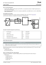
•
•
•
•
•
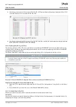
1.
2.
3.
4.
-
Subtool
Description
CAM editor
For designing CAM profiles for the servo drives.
Configuration parameter
For setting up the motor and feedback parameters, and PID settings.
Drive commissioning
For motor inertia measurement.
The detailed description of the VLT
®
Servo Toolbox functionality and the full parameter lists can be found in the
VLT® Servo Drive
System ISD 510, DSD 510, MSD 510 (VLT® FlexMotion
™
) Programming Guide
.
6.6.2 System Requirements
To install the VLT
®
Servo Toolbox software, the PC must meet the following requirements:
Supported hardware platforms: 32-bit, 64-bit.
Supported operating systems: Windows 10, Windows 11.
.NET framework version: 4.7.
Minimum hardware requirements: 512 MB RAM, Intel Pentium 4 with 2.6 GHz or equivalent, 100 MB hard disk space.
Recommended hardware requirements: Minimum 1 GB RAM, Intel Core i5/i7 or compatible.
6.6.3 Installing the VLT® Servo Toolbox Software
Administrator rights are required to install the software with the Windows operating system. If necessary, contact your system ad-
ministrator.
Procedure
Check that your system meets the system requirements specified in
Download the VLT
®
Servo Toolbox installation file from the Danfoss website.
Right-click on the .exe file and select
Run as administrator
.
Follow the on-screen instructions to complete the installation process.
6.6.4 VLT® Servo Toolbox Communication
6.6.4.1 Overview
This chapter describes the Ethernet-specific network interface settings needed by the VLT
®
Servo Toolbox. There are 2 basic com-
munication methods: direct communication and indirect communication. Their particular network settings are described in the re-
spective subchapters.
Read and perform the steps with care. Incorrect network configurations can lead to loss of connectivity of a network interface.
6.6.4.2 Firewall
Depending on the firewall settings and the fieldbus used, the messages sent and received by the VLT
®
Servo Toolbox may be
blocked by the firewall on the VLT
®
Servo Toolbox host system. This may lead to a loss of communication and the inability to com-
municate with the devices on the fieldbus. Therefore, ensure that the VLT
®
Servo Toolbox is allowed to communicate through the
firewall on the VLT
®
Servo Toolbox host system. Inappropriate changes to firewall settings may lead to security issues.
N O T I C E
When using a dedicated network interface, the VLT
®
Servo Toolbox must be allowed to communicate specifically through
this network interface.
6.6.4.3 Indirect Communication
6.6.4.3.1 Overview
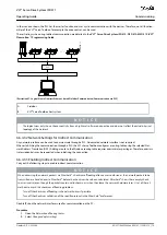
Communication between ISD 511 devices and the VLT
®
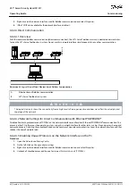
Servo Toolbox through a PLC is called indirect communication. Ethernet-
based fieldbus communication (marked A in the graphic) takes place between the PLC and the ISD 511 devices. However, there is
non-fieldbus communication between the PLC and the VLT
®
Servo Toolbox host system.
AQ377148425069en-000101
/ 130R1213
78 | Danfoss A/S © 2023.08
Commissioning
VLT® Servo Drive System ISD 511
Operating Guide

