


for descriptions and procedures for service information
available in the 15-** parameter group.
2.5 Frequency Converter Inputs and
Outputs
The frequency converter operates by receiving control
input signals. The frequency converter can also output
status data or control auxiliary devices. Control input is
connected to the frequency converter in three possible
ways. One way for frequency converter control is through
the LCP on the front of the frequency converter when
operating in local (hand) mode. These inputs include start,
stop, reset, and speed reference.
Another control source is through serial communication
from a serial bus. A serial communication protocol supplies
commands and references to the frequency converter, can
program the frequency converter, and reads status data
from the frequency converter. The serial bus connects to
the frequency converter through the RS-485 serial port or
through a communication option card.
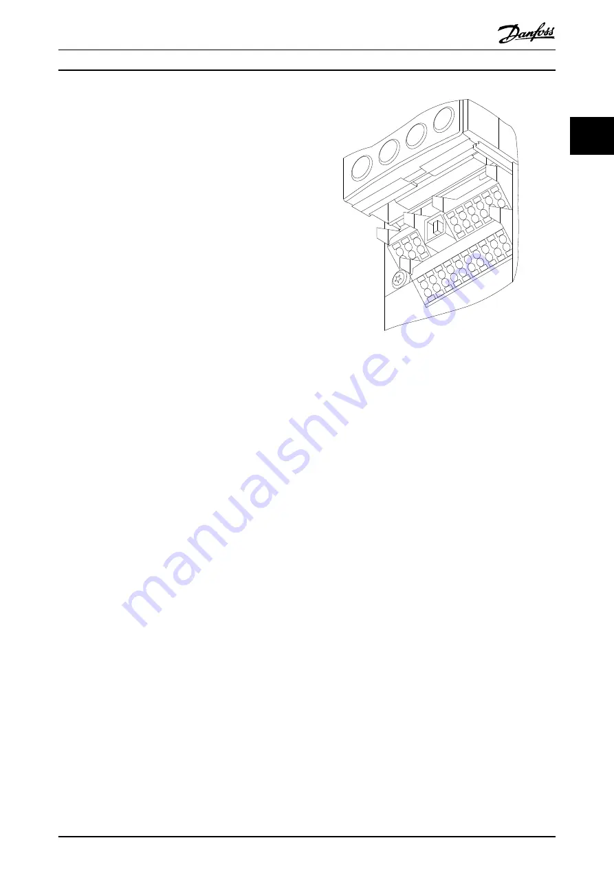
The third way is through signal wiring connected to the
frequency converter control terminals (see illustration
below). The frequency converter control terminals are
located below the frequency converter LCP. Improperly
connected control wiring can be the cause of a motor not
operating or the frequency converter not responding to a
remote input.
Terminal Descriptions
1.
Digital I/O terminals
2.
RS-485 (EIA-485) terminal
3.
Analog I/O terminals
4.
USB connector
1
4
2
3
130BA012.11
61
68
69
39
42
50
53
54
55
12
13
18
19
27
29
32
33
20
37
Illustration 2.3 Control Terminals
2.5.1 Input signals
The frequency converter can receive two types of remote
input signals: digital or analog. Digital inputs are wired to
terminals 18, 19, 20 (common), 27, 29, 32, and 33. Analog
or digital inputs are wired to terminals 53 or 54 and 55
(common). The terminal functions are set by a switch
found by removing the LCP. Some options may include
additional terminals.
Analog signals can be either voltage (0 to +10 VDC) or
current (0 to 20 mA or 4 to 20 mA). Analog signals can be
varied like dialling a rheostat up and down. The frequency
converter can be programmed to increase or decrease
output in relation to the amount of current or voltage. For
example, a sensor or external controller may supply a
variable current or voltage. The frequency converter
output, in turn, regulates the speed of the motor
connected to the frequency converter in response to the
analog signal.
Digital signals are a simple binary 0 or 1 which, in effect,
act as a switch. Digital signals are controlled by a 0 to 24
VDC signal. A voltage signal lower than 5 VDC is a logic 0.
A voltage higher than 10 VDC is a logic 1. Zero is open,
one is close. Digital inputs to the frequency converter are
switched commands such as start, stop, reverse, coast,
reset, and so on. (Do not confuse these digital inputs with
serial communication formats where digital bytes are
grouped into communication words and protocols.)
The RS-485 serial communication connector is wired to
terminals (+) 68 and (-) 69. Terminal 61 is common and
may be used for terminating screens only when the
control cable run between frequency converters, not
Operator Interface and Cont...
High Power Service Manual for Modular F Frame Drives
MG90K202 - VLT
®
is a registered Danfoss trademark
43
2
2


