


9
SEQUENCE OF
OPERATION
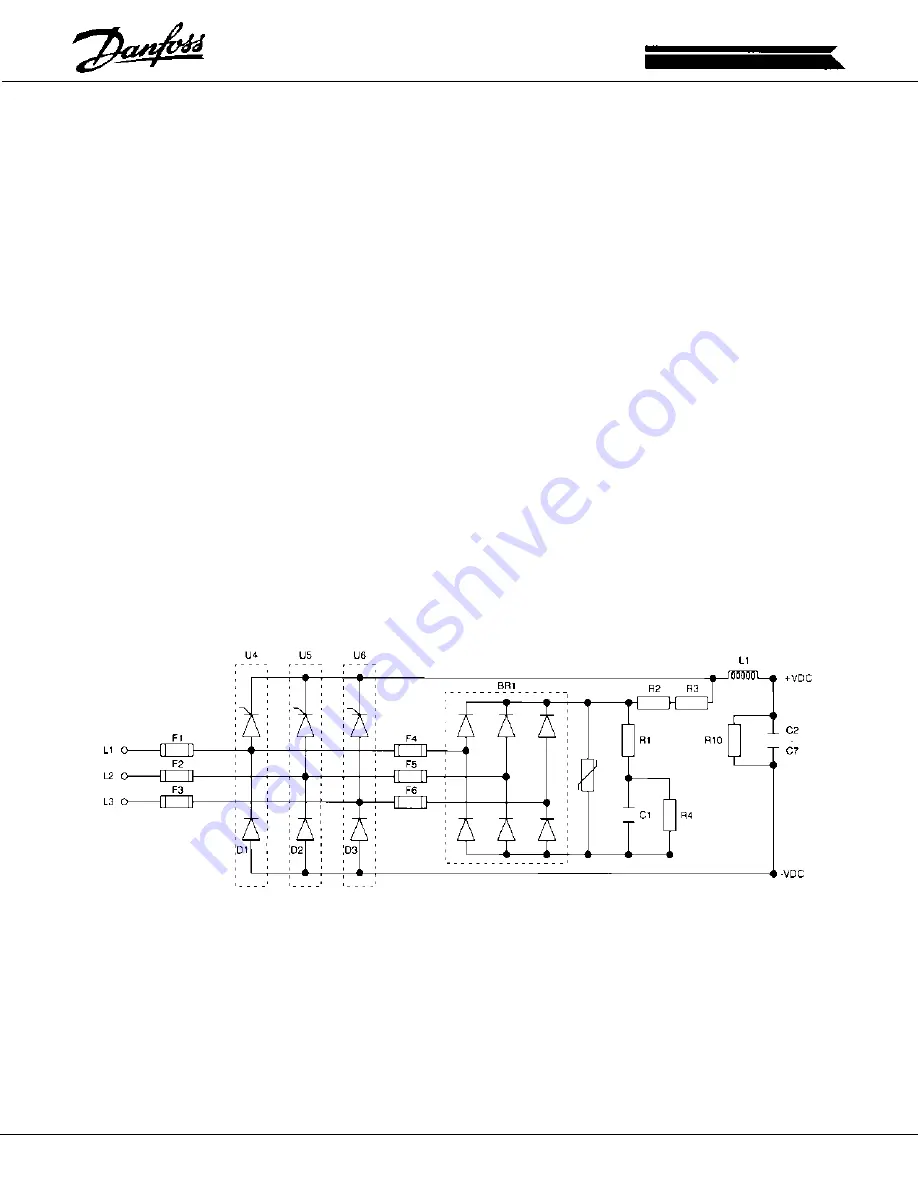
When input power is first applied, the SCR/Diode modules (input
rectifiers) are not gated so the incoming line voltage is rectified by the
soft charge rectifier (BR1). As the DC Bus capacitors charge, the inrush
current is limited by the series soft charge resistors (R2 and R3).
Following a time delay of approximately one second, the interface board
monitors the DC Bus voltage and, providing it has reached an acceptable
level, begins sending gate pulses to the SCR/Diode Modules. Once
the SCR's have been gated on, they remain in this state and the SCR/
Diode modules act as a normal rectifier. This scenario will only be
interrupted if the DC Bus fails to charge. This can be caused by
insufficient line voltage, a fault in the Power Section, a fault in the soft
charge circuit, and also by an open connection at PINS 1 and 2 of
MK15. The SCR Disable input at MK15 is provided as a means to
disable the SCR/Diode modules in the case of an external failure such
as in the Dynamic Brake option. Note that although the SCR/Diode
modules may be disabled, line voltage is still applied to the unit through
the soft charge circuit.
Providing the charging process proceeds normally, the power supplies
will come up and provide the control card and all other sections of the
unit with low voltage control power. At this time the display in the
control card will indicate the unit is ready for operation.
Following a run command and a speed reference, the control card
delivers the PWM signals (one for each phase) to the interface board.
The interface board in turn receives these three signals and creates
the six individual gate drive pulses. The gate drive pulses are sent to
the respective gate drive circuits located on the gate drive card. From
here the output power devices (IGBTS) are switched on and off to
develop the PWM waveform which is ultimately delivered to the motor.
As the unit operates, the interface board monitors the status of the
units operating condition. Currents in excess of limits, temperatures
being exceeded, and voltages out of specification will result in the
interface board responding with a fault and sending the appropriate
fault message to the control card. When a fault occurs, the interface
board will indicate the condition via a series of LED's. The control card
will also display a fault message, and in virtually all cases trip the unit
off line. Section 2 of this manual describes the fault LED's and
messages and provides direction in determining the cause and the
solution for the fault condition.