Chapter 5 Function code VFD500 high performance vector control frequency inverter user manual
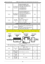
r27.20
Auxiliary
frequency
unit:0.01Hz
-
●
r27.21
UpDown offset
frequency
unit:0.01Hz
-
●
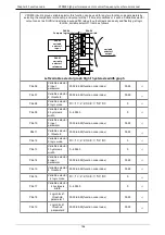
30 Group Modbus communication parameter
P30.00
Communicatio
n type
0:Modbus;
1:Canopen
0
★
P30.01
Drive Address
1
~
247
Different slaves on the same network should
set different local addresses;
0 is the broadcast address, all slave inverters
can be identified
1
★
P30.02
Modbus baud
rate
0:1200 bps; 1:2400 bps
2:4800 bps; 3:9600 bps
4:19200 bps; 5:38400 bps
6:57600 bps; 7:115200 bps
3
★
P30.03
Modbus data
format
0: 1-8-N-1
(1 start bit +8 data bits +1 stop bits )
1: 1-8-E-1
(1start bit +8 data bits +1 even 1 stop
bit)
2: 1-8-0-1
(1 star bit+8 data bits +1odd 1 stop
bits)
3: 1-8-N-2
(1 star bit+8 data bits+2 stop bits)
4: 1-8-E-2
(1 star bits+8 data bit+1 even 2 stop
bits)
5: 1-8-0-2
(1 start bit +8 data bits+1 odd 2 stop
bits)
0
★
P30.04
Modbus
response
delay
1
~
20msThe delay time of the local to answer
the master
2ms
★
P30.05
Modbus
overtime
0.0s(disabled)
~
60.0s(works for master-slave
system) When this function code effective,if
slave do not receive data from master
overtime,it will trip as Er.485
0.0s
★
r30.06
Number of
frames
received by
Modbus
Each time a frame is received, this value is
incremented by 1,0 to 65535 cycles.
-
●
r30.07
Number of
frames that
Modbus has
sent
Each time a frame is sent, this value is
incremented by 1,0 to 65,536 cycles.
-
●
r30.08
Number of
error frames
received by
Modbus
Each time an CRC error frame is received,
this value is incremented by 1,0 to 65535
cycles; it can be used to judge the degree of
communication interference.
-
●
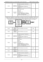
P30.09
Modbus
master-slave
option
0: Slave
1: Master(sent by broadcast )
0
★
P30.10
Slave memory
when inverter
as master
1
~
9 corresponds to 0x7001
~
0x7009
1
☆
94
Summary of Contents for VFD500 Series
Page 3: ... 3 ...


