VFD500 high performance vector control frequency inverter user manual Chapter 7 Selection guide of inverter
Accessory
◆
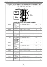
Open collector type, push-pull output type encoder wiring:
Select the encoder power supply through SW3 on the PG card, SW1 and SW2 to the OC side, as shown
below:
:
!
!
Chart 7-5 Collector open type, push-pull output type encoder DIP switch selection
When wiring, the /A, /B, /Z terminals of the PG card are not wired, and the signal output of the
encoder is connected to the A, B, and Z terminals of the PG card, as shown in the figure below.
:
!
Chart 7-6 Collector open type, push-pull output type encoder wiring diagram
◆
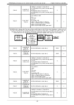
Differential output encoder wiring
:
Select the encoder power supply through SW3 on the PG card, SW1 and SW2 to the TP side, as
shown below
:
!
!
Chart 7-7 Differential output type encoder DIP switch selection
The wiring of the PG card and the encoder are connected one by one according to the silkscreen.
(
2
)
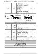
Incremental encoder PG card with Frequency division
13
/W
Encoder W-
signal
Note:UVW is
used to the
synchronous
motor
incremental
encoder, no
need wiring
when it is not
used.
14
W
Encoder
W+signal
15
/V
Encoder V-
signal
16
V
Encoder
V+signal
17
/U
Encoder U-
signal
18
U
Encoder
U+signal
-
PG
CARD
-
SHIELDING
CABLE
ENCODER
120
Summary of Contents for VFD500 Series
Page 3: ... 3 ...

