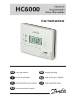
background image

TP9

Installation Instructions 
User Instructions
 
Instrucciones de instalación 
Instrucciones del usuario

Electronic programmable 
room thermostat plus 
domestic hot water timer

Ïäçãßåò åãêáôÜóôáóçò
Ïäçãßåò ÷ñÞóçò
 

Instrukcja instalacji  
Instrukcja Użytkownika

GB


®

Certification Mark

ES

GR

PL

Summary of Contents for TP9

Page 1: ...tions User Instructions Instrucciones de instalaci n Instrucciones del usuario Electronic programmable room thermostat plus domestic hot water timer Instrukcja instalacji Instrukcja U ytkownika GB Cer...

Page 2: ...g 7 13 User Instructions 14 26 Installation Instructions 27 30 Wiring 31 37 User Instructions 38 49 Installation Instructions 50 53 Wiring 54 60 User Instructions 61 72 Installation Instructions 73 76...

Page 3: ...50 60Hz Power reserve Minimum 24 hours Switching action of output relay 2 x SPDT Type 1B Switch rating 230 Vac 15 50 60Hz 3 1 A Max ambient temperature 45 C Temperature range 5 30 C or 16 30 C Dimens...

Page 4: ...efective product If date precedes June 2005 the remote sensor must also be changed First remove the wallplate from the back of the unit When fixing the wallplate remember the connections are at the to...

Page 5: ...from draughts and extraneous heat gains Remote Sensor wiring should be in 1mm2 Mains Voltage Cable not flexible cord Sensor cable must not be run parallel to mains cable in order to avoid pick up For...

Page 6: ...f the unit Locate the module on the two locating lugs on the top of the wallplate and hinge downwards to fully engage the fixing screws in the slots at the bottom of the module Tighten the screws Impo...

Page 7: ...nformation relating to the ancillary controls is obtained from the manufacturers concerned NOTE The TP9 does not have voltage free contacts therefore it is NOT suitable for connection to extra low vol...

Page 8: ...8 Typical Gravity D H W Pumped HTG TP9 Switch 1 to GRAVITY N L 1 2 3 4 5 6 HW OFF HW ON CH OFF CH ON Wiring GB...

Page 9: ...ch 1 to GRAVITY N L 1 2 3 4 5 6 HW OFF HW ON CH OFF CH ON Other Danfoss Randall products suitable for use with the above control circuit AT Cylinder Thermostat HP22 or HP28 Motorised Zone Valve with S...

Page 10: ...FF CH ON Terminals Remote Sensor N N L 3 amp fuse Looping Terminals Mains Supply Cyl Stat Boiler S R Z V in HW N N Pump N Other Danfoss Randall products suitable for use with the above control circuit...

Page 11: ...W ON CH OFF CH ON Terminals Remote Sensor N N L 3 amp fuse Looping Terminals Mains Supply Cyl Stat Boiler Pump 3 port mid position valve N N Other Danfoss Randall products suitable for use with the ab...

Page 12: ...or use with the above circuit AT Cylinder Thermostat 2 x HP22 or HP28 Motorised Zone Valve with Spring Return Actuator and SPST auxiliary switch N L 1 2 3 4 5 6 HW OFF HW ON CH OFF CH ON Terminals Rem...

Page 13: ...MPED N L 1 2 3 4 5 6 HW OFF HW ON CH OFF CH ON Terminals Remote Sensor N N L 3 amp fuse Looping Terminals Mains Supply Cyl Stat Boiler Pump F M Z V in HW N N N F M Z V in CH Other Danfoss Randall prod...

Page 14: ...rent times you have chosen and then leave it alone to do its job The best way to do this is to set low temperatures first say 18 C and then turn them up by one degree each day until you are comfortabl...

Page 15: ...after a powercut Indicates the WATER 1HR override is in operation When Central Heating is ON a flame symbol appears in the display and the red CH indicator illuminates When Hot Water is ON a tap symbo...

Page 16: ...f operating times and temperatures which often suit most people Central Heating ControlTimes andTemperatures Domestic Hot Water Times If you want to change any of these settings you can do so by follo...

Page 17: ...me and day number begin to blink in the display TIME Press and to change time press and hold to change in 10 min increments Press PROG again First time installation only When the unit is first removed...

Page 18: ...preset programmes on page 16 you don t need to do anything else Press PROG until colon flashes in display Your unit is in RUN mode and your heating and hot water will operate according to the preset...

Page 19: ...aneously see page 17 Before you change the preset programme Your installer will have set your unit to operate in either 24 hour mode or 5 2 day mode To tell which mode your unit is set press PROG unti...

Page 20: ...hen you would like your heating to go off Event 2 press the PROG button again Continue programming the central heating event times temperatures by pressing a PROG button to move to the next setting b...

Page 21: ...ent 1 3 Use the and buttons to set the temperature you want your heating to reach at this time 4 To move to the next setting i e when you would like your heating to go off Event 2 press the PROG butto...

Page 22: ...the and buttons to set the temperature you want your heating to reach at this time 8 To move to the next setting i e when you would like your heating to go off Event 2 press the PROG button again 9 C...

Page 23: ...hot water programme in the same way as the heating programme using a and buttons to alter the time b pressing the PROG button to move to the next setting Setting B 1st Off Setting C 2nd On Setting D 2...

Page 24: ...periods N B When the unit switches the CH on the HW will also switch on if the unit has been set for linked GRAVITY operation 3 Water only Switches Hot Water on and off twice a day during the summer o...

Page 25: ...he hot water is ON will extend the ON period by an hour Pressing this button when the hot water is OFF will turn the hot water ON for just one hour When the 1 HR ON button is pressed an O symbol appea...

Page 26: ...l with the clock keeping time On the 16th day of continuous loss of power the clock will stop and the display will become blank except for the colon which will be on continuously However the programme...

Page 27: ...rva de energ a M nimo 24 horas Tipo de contacto 2 x SPDT Type 1B Carga de los contactos 230 Vac 15 50 60Hz 3 1 A Temperatura ambiante m xima 45 C Rango de temperatura 5 30 C o 16 30 C Dimensiones gene...

Page 28: ...roducto defectuoso Si la fecha es anterior a junio de 2005 deber cambiarse tambi n el sensor remoto Primero retire la placa de asiento de la parte posterior de la unidad Cuandovayaafijarlaplacadeasien...

Page 29: ...a as El cableado del Sensor Remoto debe ser de 1mm2 de Cable de Tensi n de Red cable no flexible El cable del sensor no debe ir paralelo al cable de la red con el fin de evitar captaciones Para las co...

Page 30: ...loque el m dulo sobre las dos orejetas de posici n situadas en la parte superior de la placa de asiento y b jelo hasta enganchar completamente los tornillos de fijaci n en las ranuras situadas en la p...

Page 31: ...tes la informaci n espec fica relativa a los controles auxiliares NOTA El TP9 no lleva contactos libres de tensi n por tanto NO es adecuado para conectarlo a equipos de baja tensi n extra es decir 50...

Page 32: ...32 Calefacci n dom stica t pica de agua caliente bombeada por gravedad TP9 Interruptor 1 en GRAVITY GRAVEDAD N L 1 2 3 4 5 6 HW OFF HW ON CH OFF CH ON Instrucciones de instalaci n ES...

Page 33: ...en GRAVITY GRAVEDAD N L 1 2 3 4 5 6 HW OFF HW ON CH OFF CH ON Otros productos Danfoss Randall adecuados para su uso con el circuito de control anterior Termostato cil ndrico AT V lvula de zona motori...

Page 34: ...4 5 6 HW OFF HW ON CH OFF CH ON Terminals Remote Sensor N N L 3 amp fuse Looping Terminals Mains Supply Cyl Stat Boiler S R Z V in HW N N Pump N Otros productos Danfoss Randall adecuados para su uso c...

Page 35: ...CH ON Terminals Remote Sensor N N L 3 amp fuse Looping Terminals Mains Supply Cyl Stat Boiler Pump 3 port mid position valve N N Otros productos Danfoss Randall adecuados para su uso con el circuito d...

Page 36: ...ra su uso con el circuito de control anterior Termostato cil ndrico AT 2 x V lvula de zona motorizada HP22 o HP28 con impulsor de retorno por muelle e interruptor auxiliar SPST N L 1 2 3 4 5 6 HW OFF...

Page 37: ...4 5 6 HW OFF HW ON CH OFF CH ON Terminals Remote Sensor N N L 3 amp fuse Looping Terminals Mains Supply Cyl Stat Boiler Pump F M Z V in HW N N N F M Z V in CH Otros productos Danfoss Randall adecuado...

Page 38: ...rico Indica que la anulaci n de AGUA 1HR est en funcionamiento Cuando la Calefacci n Central est ENCENDIDA aparece el s mbolo de una llama en la pantalla y se enciende el indicador rojo CH Cuando el A...

Page 39: ...s instrucciones indicadas en las p ginas 42 46 En primer lugar seguir los pasos indicados en las p ginas 40 41 para ajustar la hora y la fecha correctas Setting Function Pre set A On 6 30AM b Off 8 30...

Page 40: ...ear el n mero de la hora y el d a en la pantalla HORA Pulse y para cambiar la hora pulse y mantenga pulsado el bot n para cambiar a incrementos de 10 minutos S lo para la primera instalaci n Cuando se...

Page 41: ...eg n lo indicado en la p gina 39 no necesita hacer nada m s Pulse PROG hasta que los dos puntos parpadeen en la pantalla Su unidad se encuentra en modo de FUNCIONAMIENTO y su calefacci n y agua calien...

Page 42: ...s preestablecidos El instalador habr ajustado su unidad para que funcione en modo de 24 horas o en modo de 5 2 d as Para saber en qu modo est ajustada su unidad pulse PROG hasta que el Evento 1 parpad...

Page 43: ...ue la calefacci n se apague Evento 2 pulse de nuevo el bot n PROG Siga programando las horas y temperaturas de los eventos de la calefacci n central pulsando a El bot n PROG para pasar al siguiente aj...

Page 44: ...lecer la temperatura que desea que alcance la calefacci n a esta hora 4 Para pasar al siguiente ajuste es decir cuando desea que la calefacci n se apague Evento 2 pulse de nuevo el bot n PROG 5 Siga p...

Page 45: ...atura que desea que alcance la calefacci n a esta hora 9 Para pasar al siguiente ajuste es decir cuando desea que la calefacci n se apague Evento 2 pulse de nuevo el bot n PROG 10 Siga programando las...

Page 46: ...del mismo modo que el programa de la calefacci n utilizando a Los botones y para cambiar la hora b Pulsando el bot n PROG para pasar al siguiente ajuste Ajuste B 1st Off Ajuste C 2nd On Ajuste D 2nd...

Page 47: ...B Cuando la unidad activa la CH el HW tambi n se activar si la unidad se ha ajustado para que funcione en modo de GRAVEDAD conectado 3 S lo agua Activa y desactiva el Agua caliente dos veces al d a du...

Page 48: ...caliente est activada se ampliar una hora el per odo de funcionamiento Si se pulsa este bot n cuando el agua caliente est desactivada se activar durante s lo una hora Cuando se pulsa el bot n 1 HR ON...

Page 49: ...el tiempo En el d a 16 de p rdida continua de alimentaci n el reloj se detendr y la pantalla se pondr en blanco excepto los dos puntos que seguir n vi ndose continuamente No obstante se recordar n las...

Page 50: ...50 TP9 M 230 Vac 15 50 60Hz 24 2 x SPDT Type 1B 230 Vac 15 50 60Hz 3 1 A 45 C 5 30 C 16 30 C x x 136 x 88 x 32 60 x 45 x 21 EN60730 2 9 2 5Kv 75 C Degree 2 IP30 1 min A GR...

Page 51: ...3 TP9 2005 C L 4 Clearance for screwdriver access Surface fixed cable bottom entry knockouts Rear entry cable access N looping terminals Wall or Plaster box fitting Terminal block Outline of unit 30mm...

Page 52: ...52 1 5 m 1 mm2 54 60 24 5 2 5 2 PUMPED 24 2 3 24 HR GRAVITY 1 GRAVITY GR...

Page 53: ...53 5 30 C 16 30 C TP9 4 GR...

Page 54: ...54 TP9 50 Volt 1 mm2 50 GR...

Page 55: ...55 9 1 GRAVITY N L 1 2 3 4 5 6 HW OFF HW ON CH OFF CH ON 3 GR...

Page 56: ...56 9 1 GRAVITY N L 1 2 3 4 5 6 HW OFF HW ON CH OFF CH ON Danfoss Randall AT HP22 HP28 SPST 3 GR...

Page 57: ...TP9 1 PUMPED Danfoss Randall AT HP28C SPST N L 1 2 3 4 5 6 HW OFF HW ON CH OFF CH ON Terminals Remote Sensor N N L 3 amp fuse Looping Terminals Mains Supply Cyl Stat Boiler S R Z V in HW N N Pump N 3...

Page 58: ...P9 1 PUMPED Danfoss Randall AT HS3 N L 1 2 3 4 5 6 HW OFF HW ON CH OFF CH ON Terminals Remote Sensor N N L 3 amp fuse Looping Terminals Mains Supply Cyl Stat Boiler Pump 3 port mid position valve N N...

Page 59: ...D Danfoss Randall AT 2 x HP22 HP28 SPST N L 1 2 3 4 5 6 HW OFF HW ON CH OFF CH ON Terminals Remote Sensor N N L 3 amp fuse Looping Terminals Mains Supply Cyl Stat Boiler Pump S R Z V in HW N N N S R Z...

Page 60: ...P9 1 PUMPED N L 1 2 3 4 5 6 HW OFF HW ON CH OFF CH ON Terminals Remote Sensor N N L 3 amp fuse Looping Terminals Mains Supply Cyl Stat Boiler Pump F M Z V in HW N N N F M Z V in CH Danfoss Randall AT...

Page 61: ...61 TP9 6 TP9 WATER 1HR ON CH HW RUN ON OFF AM PM RUN ON OFF AM PM GR...

Page 62: ...P9 65 69 63 64 A On 6 30AM b Off 8 30AM C On 5 30PM d Off 10 30PM C C 1 06 30 20 1 07 00 20 2 08 30 16 2 10 00 16 3 12 30 19 3 12 00 19 4 13 30 16 4 14 00 16 5 17 30 21 5 17 00 21 6 22 30 16 6 22 30 1...

Page 63: ...63 3 12 00 1 PROG 10 M RESET GR...

Page 64: ...64 PROG MO TU 62 PROG RUN 5 2 GR...

Page 65: ...65 ON OFF PROG 63 24 5 2 PROG 1 Event 1 24 66 5 2 67 68 GR...

Page 66: ...66 1 PROG 1 Event 1 1 2 2 PROG a PROG b c 3 PROG RUN 4 69 24 GR...

Page 67: ...67 1 PROG 1 MOTUWETHFR 2 1 3 4 2 PROG 5 3 4 5 6 2 4 5 2 GR...

Page 68: ...68 6 PROG 1 SASU 7 1 8 9 2 PROG 10 3 4 5 6 7 9 11 PROG RUN 12 69 GR...

Page 69: ...69 PROG A On a b PROG B Off C On D Off PROG RUN GR...

Page 70: ...70 TP9 3 1 2 CH HW GRAVITY 3 ON 16 C CH GR...

Page 71: ...71 TP9 1HR 1 HR ON O GR...

Page 72: ...72 15 16 15 12 00 MO 5 2 63 64 GR...

Page 73: ...y kacja TP9 Zasilanie 230 Vac 15 50 60Hz Rezerwa zasilania co najmniej 24 godziny Typy wbudowanych przeka nik w 2 x SPDT Type 1B Obci alno styk w 230 Vac 15 50 60Hz 3 1 A Maksymalna temperatura 45 C Z...

Page 74: ...zdalnej Najpierw zdj pokryw z ty u jednostki Podczas mocowania pokrywy pami ta i po czenia znajduj si u g ry oraz e pionowa linia rodkowa urz dzenia musi znajdowa si w po o eniu pokazanym jako C L w...

Page 75: ...de ciep a Oprzewodowanie czujnika pracy zdalnej nale y wykona przy u yciu przewodu sieciowego 1mm2 nie u ywa przewodu gi tkiego Przew d czujnika nie mo e biec r wnolegle do przewodu sieciowego gdy stw...

Page 76: ...hipotermia Aby zmieni ustawienie fabryczne przestawi prze cznik 4 z ty u urz dzenia Umie ci modu na dw ch uchach ustalaj cych u g ry pokrywy i przechyli ca o w d aby w pe ni zaczepi ruby mocuj ce w ot...

Page 77: ...tkowych uk ad w sterowania od odno nych producent w UWAGA TP9 nie posiada styk w beznapi ciowych w zwi zku z czym NIE nadaje si do pod czenia do sprz tu zasilanego napi ciem bardzo niskim np 50 V Czuj...

Page 78: ...78 Typowe grawitacyjne domowe ogrzewanie ciep ej wody wymuszane pomp TP9 prze cznik 1 na GRAVITY N L 1 2 3 4 5 6 HW OFF HW ON CH OFF CH ON Instrukcja instalacji PL...

Page 79: ...znik 1 na GRAVITY N L 1 2 3 4 5 6 HW OFF HW ON CH OFF CH ON Inne produkty Danfoss Randall kompatybilne z ww obwodem steruj cym Termostat z cylindrem AT Zaw r strefowy HP22 lub HP28 obs ugiwany silnicz...

Page 80: ...OFF HW ON CH OFF CH ON Terminals Remote Sensor N N L 3 amp fuse Looping Terminals Mains Supply Cyl Stat Boiler S R Z V in HW N N Pump N Inne produkty Danfoss Randall kompatybilne z ww obwodem steruj...

Page 81: ...CH ON Terminals Remote Sensor N N L 3 amp fuse Looping Terminals Mains Supply Cyl Stat Boiler Pump 3 port mid position valve N N Inne produkty Danfoss Randall kompatybilne z ww obwodem steruj cym Ter...

Page 82: ...odem steruj cym Termostat z cylindrem AT 2 x Zaw r strefowy HP22 lub HP28 obs ugiwany silniczkiem ze spr ynowym powrotnym mechanizmem uruchamiaj cym i prze cznikiem dodatkowym SPST N L 1 2 3 4 5 6 HW...

Page 83: ...e cznik 1 na PUMPED N L 1 2 3 4 5 6 HW OFF HW ON CH OFF CH ON Terminals Remote Sensor N N L 3 amp fuse Looping Terminals Mains Supply Cyl Stat Boiler Pump F M Z V in HW N N N F M Z V in CH Inne produk...

Page 84: ...grzewanie centralne jest w czone ON na wy wietlaczu pojawia si symbol p omienia a czerwony wska nik CH zapala si Gdy woda ciep a jest w czona ON na wy wietlaczu pojawia si symbol kranu a wska nik HW z...

Page 85: ...a stronach 88 92 Najpierw wykonaj czynno ci opisane na stronach 86 87 aby ustawi w a ciw godzin i dat Setting Function Pre set A On 6 30AM b Off 8 30AM C On 5 30PM d Off 10 30PM Nie dotyczy sytuacji w...

Page 86: ...umer godziny i data nie zaczn miga na wy wietlaczu TIME Nacisn oraz w celu zmiany godziny nacisn i przytrzyma aby zmieni w odst pach 10 minutowych Tylko pierwsza instalacja Gdy jednostka zostanie wyj...

Page 87: ...awione programy strona 85 nie musisz wykonywa adnych dalszych czynno ci Naciska PROG dop ki na wy wietlaczu nie zacznie miga dwukropek Pa stwa urz dzenie jest uruchomione w trybie RUN za ogrzewanie i...

Page 88: ...anim zmienisz programy ustawione wst pnie Pa stwa instalator ustawi urz dzenie na prac w trybie 24 godzin lub 5 2 dni Aby wskaza tryb ustawienia urz dzenia naciska PROG dop ki na wy wietlaczu nie poja...

Page 89: ...by wy czone Event 2 ponownie nacisn przycisk PROG Kontynuowa programowanie godzin i temperatur zdarze centralnego ogrzewania poprzez naciskanie a Przycisku PROG w celu przej cia do nast pnego ustawien...

Page 90: ...raz w celu ustawienia temperatury kt r ogrzewanie ma osi gn o tej godzinie 4 Aby przej do nast pnego ustawienia np godziny o kt rej ogrzewania ma by wy czone Event 2 ponownie nacisn przycisk PROG 5 Da...

Page 91: ...temperatury kt r ogrzewanie ma osi gn o tej godzinie 9 Aby przej do nast pnego ustawienia np godziny o kt rej ogrzewania ma by wy czone Event 2 ponownie nacisn przycisk PROG 10 Dalej programowa godzi...

Page 92: ...tak samo jak program nagrzewania za pomoc a Przycisk w oraz w celu zmiany godziny b Naciskania przycisku PROG w celu przej cia do nast pnego ustawienia Ustawienie B 1 Off Ustawienie C 2 On Ustawienie...

Page 93: ...zczeniu gdy budynek jest pusty przez d u szy czas N B Gdy jednostka w czy CO CW r wnie zostanie w czone je eli jednostk ustawiona na powi zan prac GRAVITY 3 Tylko woda W cza i wy cza wod ciep dwa razy...

Page 94: ...kres w czenia o jedn godzin Naci ni cie tego przycisku gdy woda ciep a jest wy czona OFF w czy wod ciep na jedn godzin Po naci ni ciu przycisku 1 HR ON na wy wietlaczu pojawi si symbol O Ogrzewanie Ab...

Page 95: ...zin W 16 tym kolejnym dniu od utraty zasilania zegar zatrzyma si a wy wietlacz si wy czy ci gle w czony pozostanie tylko symbol dwukropka jednak e zaprogramowane godziny i temperatury zostan zachowane...

Page 96: ...96 www danfoss com BusinessAreas Heating Part No 6578 Issue 02 05 06...

Reviews: