Application guidelines
30
FRCC.PC.021.A5.22
CAN-Bus and Modbus RS485 Communication
General hardware network and
communication protocol
Dipswitches
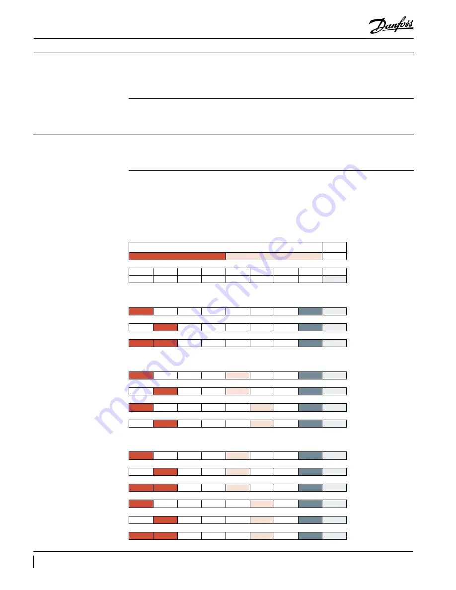
Compressor address set-up
for CAN-Bus and Modbus
CAN-Bus and RS485 hardware network must
follow the recommendations described in the
document DKRCC.PS.RIO.F1.02.
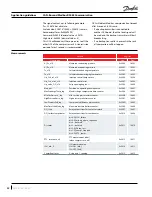
CAN-Bus and Modbus RS485 Communication
protocol parameters are as follow:
a. CANOPEN: nodeID: 1, baudrate: 50K
b. Modbus RS485: ID: none, baudrate: 9600,
databits: 8, partity: NONE, stop bits: 1.
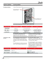
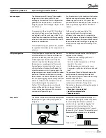
Dipswitches on OCS are set at 0 by default
and have to be changed following the
recommendation below:
Before changing the compressor address on
dipswitches, the OCS must be powered-off.
A valid NodeID has to be set as binary code.
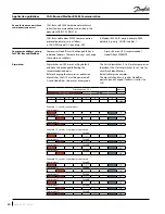
The 4 first dipswitches (1 to 4) are for compressor
identifiant, the 3 last dipswitches (5 to 7) are for
circuit/rack identification.
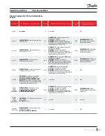
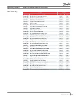
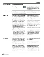
Below tables give examples.
The dipswitch address is read as NodeID at
power-up and changed if address is valid (1 to
125).
Compressor NodeID must be changed to have
individual address. There are two ways to change
the compressor address:
• Dipswitches on OCS (recommended).
• NodeID from MMIMYK
Dipswitches on OCS
address
Compressor
Circuit
1
2
3
4
5
6
7
8
default
Example 1: 1 circuit, 3 compressors
Compressor 1
1
1
Compressor 2
1
2
Compressor 3
1
1
3
Example 2: 2 circuits, 2 compressors per circuit
Compressor 1
Circuit A
1
1
17
Compressor 2
Circuit A
1
1
18
Compressor 1
Circuit B
1
1
33
Compressor 2
Circuit B
1
1
34
Example 3: 2 circuits, 3 compressors per circuit
Compressor 1
Circuit A
1
1
17
Compressor 2
Circuit A
1
1
18
Compressor 3
Circuit A
1
1
1
19
Compressor 1
Circuit B
1
1
33
Compressor 2
Circuit B
1
1
34
Compressor 3
Circuit B
1
1
1
35

