background image

©

 Danfoss A/S (RA Marketing/MWA), Nov. 08 

RS8FE102, 080R9278


7

OPTYMA

TM

 Control three-phase 

Operation and Maintenance Guide

The OPTYMA

TM

 Control three-phase unit is supplied with:

Standard assembly kit

Installation

•   4  rubber  washers,  to  be  fitted  between  the 


  fixing screws and the housing  back panel

•   1 operation and maintenance guide
•   1 wiring instruction.
•   1 drilling layout.
•  

2 sensors

•   Each  control  is  designed  to  be  wall-mounted; 


  please  select  an  appropriate  fixing  method  
  depending on the weight.

•   Install the device in places where the protection 


  rating is observed.

•   To  effect  the  correct  electrical  connection  and 


  maintain  the  protection  rating,  use  appropriate  
  cable glands and plugs to ensure a good seal. 

Mechanical assembly

•   Install  the  device  at  an  appropriate  height  for


  ease of use and maintenance. The installer must 
  not be put at risk when working on the panel.
  The device must be located at a height of between  
  0.6 and 1.7 m from the ground.

•   Install the device away from fire and heat sources


  and protect from the weather if necessary.

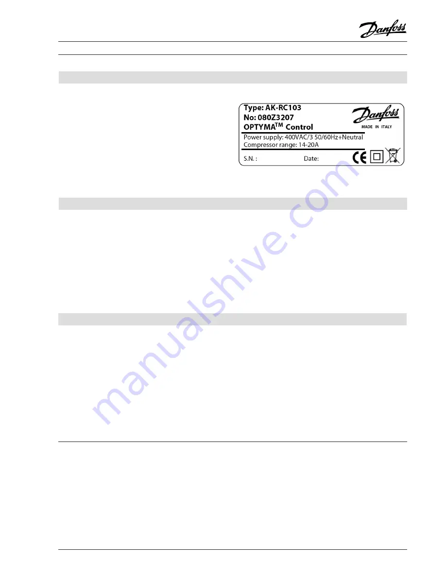
A label bearing the following information is affixed to 
the side of the product described in this manual

•   Name of manufacturer
•   Product type and code number
•   Product name
•   Power supply
•   Compressor range
•   Serial number (10 digits)
•   Date (Day/Month/Year)

Identification data

Each  control  is  carefully  packaged  to  ensure  that 
it  arrives  undamaged  under  normal  transport 
conditions.  Prior  to  transportation,  please  ensure 
that:
•   No objects or loose parts are inside the control.
•   The door is correctly closed and locked.
•   If  the  original  packaging  is  not  used,  the  
  product  is sufficiently packaged to allow safe  
  transportation

Transport and storage

The storage room must be of a suitable temperature

and  low  humidity;  avoid  contact  between  the 

electrical control and aggressive contaminants that 
could impair functioning and electrical safety.

Example:

Installation to be done by authorised person only!

Summary of Contents for OPTYMA

Page 1: ...REFRIGERATION aIR CONDITIONING DIVISION OPTYMATM Control Three phase MAKING MODERN LIVING POSSIBLE Operation and Maintenance Guide...

Page 2: ......

Page 3: ...efore use 13 Calibrating the compressor motor circuit breaker 14 Closing the control 15 Control panel 16 Front keypad 16 LED display 17 General 17 Symbols used 17 Setting and displaying the setpoints...

Page 4: ...control with wide LED display and easy to use buttons Display and adjustment of cold room temperature accurate to 0 1 C Display of evaporator temperature from para meter System control activation deac...

Page 5: ...motor circuit breaker Adjustable motor circuit breaker Defrosting electrical electrical Status indicators LED display LED display Alarm signals LED buzzer LED buzzer Inputs Ambient probe EKS 221 code...

Page 6: ...6 RS8FE102 080R9278 Danfoss A S RA Marketing MWA Nov 08 OPTYMATM Control three phase Operation and Maintenance Guide Overall dimensions Dimensions in mm Connection diagrams...

Page 7: ...el The device must be located at a height of between 0 6 and 1 7 m from the ground Install the device away from fire and heat sources and protect from the weather if necessary A label bearing the foll...

Page 8: ...MATM Control three phase Operation and Maintenance Guide 1 Lift the transparent cover protecting the general magnetothermic circuit breaker Installing the unit 2 Remove the screw cover on the right ha...

Page 9: ...de 4 Close the transparent protection cover Installing the unit continued 5 Open the front of the housing lift it and slide the two hinges out as far as they will go 6 Bend the hinges and rotate the f...

Page 10: ...eze both sides of each hinge together to remove them from their seats and then completely remove the front panel Installing the unit continued 8 Using a screwdriver tap out the tabs in the 4 holes in...

Page 11: ...supply wiring and signal wiring probes sensors and digital inputs in the same raceways or ducts Do not use multi polar cables which have wires connectedtoinductive powerloadsandsignalling wires e g p...

Page 12: ...2 Bend the hinges and rotate the front panel downwards 180 to gain access to the inside of the housing and then reconnect the electronic card connector 3 When using Alarm Aux relay connect the wiring...

Page 13: ...motor circuit breaker for the compressor if present correctly as shown on the following pages After powering up the control please check the correct current absorption on the loads and after it has b...

Page 14: ...on Calibrating the compressor motor circuit breaker 2 Calibrate the motor circuit breaker based on the measured absorption The set up value must not exceed that recommended by the compressor manufactu...

Page 15: ...ousing seal is located securely in its seat Closing the control 2 Tighten the front panel using the 4 screws making sure the rubber washers are used on the head of each screw Replace the screw cover o...

Page 16: ...tion and Maintenance Guide Control panel Front keypad AUXILIARY RELAY CONTROL on the version with alarm relay controls the relay manual if parameter AU 1 UP MUTE WARNING BUZZER STAND BY The LED flashe...

Page 17: ...ly modified SETPOINT parameters The second programming level Level 2 is for general parameter programming of the various controller operating modes It is not possible to access the Level 2 programming...

Page 18: ...nd of defrost setpoint Defrosting will not take place if the temperature detected by the defrost sensor is greater than d2 If the sensor is faulty defrosting is timed 35 45 C 15 C d3 Max defrost durat...

Page 19: ...F3 Fan status with compressor off 0 fans run continuously 1 fans only run when compressor is working 1 F4 Fan pause during defrost 0 fans run during defrost 1 fans do not run during defrost 1 dE Sens...

Page 20: ...y set point 1 display set point AUX light access 2 access to programming not permitted 3 access to second level programming not permitted 3 PA Password see P1 for the type of protection 0 999 0 not ac...

Page 21: ...AU parameter must never be set at 4 as the PUMP DOWN function is made electromechanically inside the panel Password function The protection function is activated when parameter PA is set with a value...

Page 22: ...front panel as described on page 8 Alarm AUX RELAY SWITCHING Only follow these instructions if alarm aux relay is not functioning 2 Bend the hinges and rotate the front panel downwards 180 to gain acc...

Page 23: ...in position 2 1 and set level 2 variable AU with the values 1 2 or 5 according to the desired function Terminal blocks for free voltage contact on configurable relay are 16 and 17 on the electronic ca...

Page 24: ...erly If the problem persists replace the sensor E2 Eeprom alarm An EEPROM memory alarm has been detected All outputs except the alarm are deactivated Switch unit off and back on again E8 Man in cold r...

Page 25: ...circuits are present Reinsert then magnetothermic circuit breaker verifying all the absorptions to identify any anomalies Circuit protection fuse on the transformer intervention Replace the fuse glas...

Page 26: ...voltage free Prevent unauthorized personnel accessing the intervention area Display suitable notices to indicate Device isolated for maintenance Wear suitable work clothing overalls gloves shoes head...

Page 27: ...ole magnetothermic circuit breaker 6 Front panel opening hinges 7 Front cover in transparent polycarbonate 8 Transparent polycarbonate screw cover 9 Auxiliary circuits transformer N B containing glass...

Page 28: ...ode no OPYTMATM Control three phase 4 HP including two sensors 4 5 6 3 A 080Z3201 OPYTMATM Control three phase 4 HP including two sensors 7 10 A 080Z3202 OPYTMATM Control three phase 7 5 HP including...

Reviews: