background image

Installation

4.6 Phase sequence 

4.7 Brazed connections

Optyma

 Plus INVERTER units are equipped with 

variable speed scroll compressors for which 
proper phase sequence is compulsory in order to 
secure rotation in right direction and therefore 
compression.

The phase sequence has to be secured between 
the drive and compressor.
(The phase sequence between network and unit 
drive is of no influence on the compressor rotation 
direction).

NOTICE

 Refrigerant connections, brazing and 

flange connections has to be done by a
qualified installer according to EN378. 

The unit is supplied with an positive protective 
pressure of Nitrogen (1 bar). 
The use of substances containing chlorine, mineral 
oil or other chemicals is not allowed.

Piping has to be designed to avoid vibrations, 
either through flexibility or piping
brackets. Furthermore piping has to be done in 
such a way that oil return for the
compressor is ensured and the risk of liquid slug 
over in compressor is eliminated.

Only use clean and dehydrated refrigeration grade 
copper tubing. Tube-cutting must be
carried out so as not to deform the tubing 
roundness and to ensure that no foreign debris
remains within the tubing. Only refrigerant grade 
fittings should be used and these must be of
both a design and size to allow for a minimum 
pressure drop through the completed assembly.
Follow the brazing instructions bellow. Never drill 
holes into parts of the pipe-work where filings 
and particles cannot be removed. Even during 
installation, if the system is left for
any reasonable period of time (say 1 hour), pipes 
should be re-capped to prevent moisture and 
contaminant from entering the system.

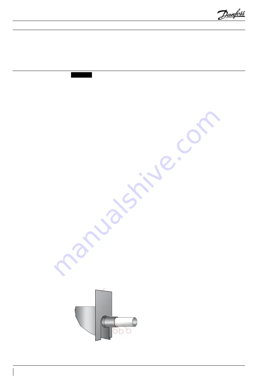
Liquid/suction tubes are extended from 
the condensing unit housing, therefore we 
recommend to isolate the housing by using a heat 
shield and/or a heat-absorbent compound (e.g. 
wet cloth) on the copper tubing. Use a double-
tipped torch.

heat shield

C B

A

For brazing the suction and liquid line 
connections, the following procedure is advised:
•  Make sure that no electrical wiring is connected 

to the compressor.

•  Use brazing material with a minimum of 5% silver 

content.

• Fit the copper tube into the unit tube.
•  Apply heat evenly to area A until the brazing 

temperature is reached. Move the torch to 
area B and apply heat evenly until the brazing 
temperature has been reached there as well, and 
then begin adding the brazing material. Move 
the torch evenly around the joint, in applying 
only enough brazing material to flow the full 
circumference of the joint.

•  Move the torch to area C only long enough to 

draw the brazing material into the joint.

•  Remove all remaining flux “once the joint has 

been soldered” with a wire brush or a wet cloth. 

Remaining flux would cause corrosion of the 
tubing. Ensure that no flux is allowed to enter into 
the tubing. Flux is acidic and can cause substantial 
damage to the internal parts of the system and 
compressor.

The polyolester oil used in VLZ compressors 
is highly hygroscopic and will rapidly absorb 
moisture from the air. Condensing unit must 
therefore not be left open to the atmosphere for 
a long period of time. Unit fitting plugs shall be 
removed just before brazing. Condensing unit 
should always be the last component brazed into 
the system.
Before eventual unbrazing of the compressor or 
any system component, the refrigerant charge 
must be removed from both the high- and 
low-pressure sides. Failure to do so may result in 
serious personal injury. Pressure gauges must be 
used to ensure all pressures are at atmospheric 
level. 
For more detailed information on the appropriate 
materials required for brazing or soldering, please 
contact the product manufacturer or distributor. 
For specific applications not covered herein, please 
contact Danfoss for further information.

It is compulsory to braze with a protective 
atmosphere of nitrogen inside the piping.
Nitrogen displaces the air and prevents the 
formation of copper oxides in the system.

24

FRCC.PC.044.A6.02

Application Guidelines

Summary of Contents for Optyma Plus

Page 1: ...Optyma Plus INVERTER Stepless capacity modulation from 30 to 100 rps in a simple plug and play package Application guidelines 2018 EcoDesign cc danfoss com OptymaTM by Danfoss...

Page 2: ......

Page 3: ...when OFF 23 4 6 Phase sequence 24 4 7 Brazed connections 24 4 8 High pressure transmitter connection 25 System design recommendations 26 5 1 Piping design 26 5 2 Evacuation 27 5 3 Refrigerant charge 2...

Page 4: ...tarting operation and maintenance of Optyma Plus INVERTER condensing units This guideline is not intended to replace the system expertise available from system manufacturers In addition to this instru...

Page 5: ...geration applications in the range of 2kW to 9kW Standard equipment features Variable speed compressor scroll with acoustic housing and crankcase heater Compressor drive with EMI filter MCHX condenser...

Page 6: ...1F0075 18 118U3259 19 118U3243 20 118U3256 21 118U3258 22 118U3887 23 118U3255 24 118U3261 25 118U3241 02 26 118U3264 27 MANIFOLD_A6E 28 118A0632001 29 118A05930001 30 118U3431001 31 118U34320002 32 1...

Page 7: ...VL variable speed scroll VLZ compressor 7 Version P01 8 Electrical code E Compressor 400 V 3 phase 50 Hz fan 230 V 1 phase 50 Hz OP MPPM044VVLP01E Code Number 114X4334 Application MBP IP 54 Refrigeran...

Page 8: ...23Z5045 014F0174 009G7053 009G7054 118U3722 118U3721 084N0003 084N2007 118U3485 OP MPLM044 OP MPPM044 120G0156 118U3494 118U3829 118U3476 023Z5045 014F0174 009G7053 009G7054 118U3722 118U3721 084N0003...

Page 9: ...2 00 38 1956 2427 2983 3632 43 50 27 2988 3751 4643 5674 6854 72 3 41 3 32 2812 3542 4393 5378 6504 1599 2 22 38 3279 4079 5003 6061 43 3051 3803 4674 5674 75 27 4374 5503 6805 8291 9973 72 9 41 9 32...

Page 10: ...871 43 50 27 3258 4080 5029 6116 7351 71 9 40 9 32 3069 3858 4766 5804 6984 1698 2 27 38 3577 4435 5416 6529 43 3330 4147 5078 6135 75 27 4776 5970 7334 8878 10612 72 5 41 5 32 4503 5648 6951 8425 100...

Page 11: ...6 1794 2 17 38 2854 3533 3937 5215 6236 43 2590 3215 3937 4766 5711 75 27 4962 6087 7381 8853 10511 74 4 43 4 32 4610 5659 6866 8240 9790 2813 2 01 38 4169 5126 5672 7481 8899 43 3784 4662 5672 6826 8...

Page 12: ...50 27 3091 3846 4713 5699 6812 73 8 42 8 32 2896 3616 4442 5381 6441 1748 2 07 38 3327 4102 4983 5977 43 3076 3806 4637 5577 75 27 4505 5569 6792 8183 9752 74 4 43 4 32 4227 5238 6396 7713 9200 2718 1...

Page 13: ...Product description 2 9 Layout OP MPLM028 035 044 OP MPPM028 035 044 13 FRCC PC 044 A6 02 Application Guidelines...

Page 14: ...9 3 kW demand at its maximum speed and at the same time condensing unit capacity at minimum speed minimum capacity 3 kW is not higher than necessary cooling capacity for the smallest evaporator 3 kW E...

Page 15: ...its are guaranteed 0 10 20 30 40 50 60 5 15 25 35 45 55 Ambient temperature C Operating Map R407F A 20 10 0 10 20 25 15 5 5 15 Evaporating temperature C 30 rps 100 rps SH10K 50 rps 100 rps C Te 10 C T...

Page 16: ...LpMinOnTime And the value for Min on time for the compressor will be set to the largest of the values of c94 MinLpOnTime and c01 Min on time The CDS803 drive forces the compressor to 50rps see Optyma...

Page 17: ...shall not be done in facilities containing flammable gasses or in installation containing flammable gasses NOTICE Special attention should be paid if unit needs to be installed close to the sea as th...

Page 18: ...9A set If another refrigerant is to be used refrigerant parameter o30 needs to be changed refer to description in Controller application manual Parameters for high and low pressure cut outs are preset...

Page 19: ...e Switch B4 Low Pressure Switch C1 Run Capacitor Fan F1 Fuse Control Circuit K1 Contactor M1 Compressor M2 Fan Motor Q1 Main Switch R1 Ambient Temp Sensor R2 Discharge Temp Sensor R3 Suction Temp Sens...

Page 20: ...11 drive start and wire 25 room thermostat and put them together Remove wire 53 and 55 from drive terminals and connect the attached 10kOhm potentiometer R8 as below wire 1 to drive terminal 55 wire...

Page 21: ...Speed Controller Pressure Switch C1 Run Capacitor Fan F1 Fuse Control Circuit K1 Contactor M1 Compressor M2 Fan Motor Q1 Main Switch R1 Ambient Temp Sensor R2 Discharge Temp Sensor R3 Suction Temp Sen...

Page 22: ...Installation Picture1 Normal wiring Picture2 Emergency wiring 22 FRCC PC 044 A6 02 Application Guidelines...

Page 23: ...or serious injury The digital inputs are not a safety switch They do not disconnect the frequency converter from the mains Do not remove mains connections compressor connections or other power connect...

Page 24: ...at shield C B A For brazing the suction and liquid line connections the following procedure is advised Make sure that no electrical wiring is connected to the compressor Use brazing material with a mi...

Page 25: ...stem pressure to the transmitter 1 Valve In from receiver 2 Valve Out to evaporator 3 Service port for safety devices 4 Service port for transmitter or service only A Valve fully closed Valve spindle...

Page 26: ...re a good oil return within 8 to 12 m s in vertical risers In horizontal pipes this velocity can decrease down to 4 m s The use of U trap and double suction risers is often required These suction rise...

Page 27: ...a minimum vacuum of 500 microns 0 67 mbar NOTICE The evacuation procedure is based upon achieving an actual system Vacuum standard and is NOT TIME DEPENDENT Evacuate the installation down to 0 67 mbar...

Page 28: ...inal condition during operation Next steps can be followed for proper charging or the system keep system working under the max load conditions all evaporators working maximum air liquid flow via evapo...

Page 29: ...the oil level should be checked and topped up if necessary When the compressor is running under stabilized conditions the oil level must be visible in the sight glass The presence of foam filling in...

Page 30: ...ess on these buttons Press short the middle button to show the value of the selected Parameter Press afterwards the upper or lower button to change the value of the selected parameter A long press on...

Page 31: ...the refrigerant Control of condensing temperature Control of fan speed On off control or speed regulation of the compressor Control of heating element in crankcase Liquid injection into economizer po...

Page 32: ...be stopped and the fan will be set to 100 When the signal is once again OK at the DI3 input the regulation will resume During regulation the internal low pressure monitoring function will cut out the...

Page 33: ...0 0 bar 2 3 Min compressor speed c46 30 rps 70 rps 30 rps Start speed for compressor and min speed for high condensing temperatures c47 30 rps 70 rps 50 rps Max compressor speed c48 50 rps 100 rps 100...

Page 34: ...working range Ps min value o20 1 bar 5 bar 1 Pressure transmitter working range Ps max value o21 6 bar 200 bar 12 Refrigerant setting 13 User defined 19 R404A 20 R407C 21 R407A 37 R407F 40 R448A 41 R...

Page 35: ...x 1 on closed u63 Status on relay to heating element in crank case 1 on closed u71 Status on high voltage input DI3 1 on 230 V u87 Readout condensing pressure in temperature U22 C Readout pressure Ps...

Page 36: ...etc Step 2 Rinse Do not use any chemicals including those advertised as coil cleaners to wash microchannel heat exchangers They can cause corrosion Rinse only with water Hose the MCHE off gently pref...

Page 37: ...Service and maintenance 7 4 Access ports Charging port liquid line initial charge 4kg Charging port suction line adjustment of refrigerant charge 37 FRCC PC 044 A6 02 Application Guidelines...

Page 38: ...ccording to weight It is recommended not to open the packaging before the unit is at the final place for installation Handle the unit with care The packaging allows for the use of a forklift or pallet...

Page 39: ...rigerant or oil not specified by Danfoss as suitable for the unit will lead to annulment of warranty from Danfoss A S side if the refrigerant or oil are not approved in writing by Danfoss Annulment of...

Page 40: ...if below Evaporator Cooling capacity kW Evaporating pressure bar temperature C Superheat at evaporator outlet K Type of expansion valve used Thermostatic TEV electronic EEX Compressor Suction gas tem...

Page 41: ......

Page 42: ...ioned us as distinct variable speed technology specialists Today we operate from engineering and manufacturing facilities spanning across three continents FRCC PC 044 A6 02 Danfoss DCS CC 2018 06 Our...

Reviews: