


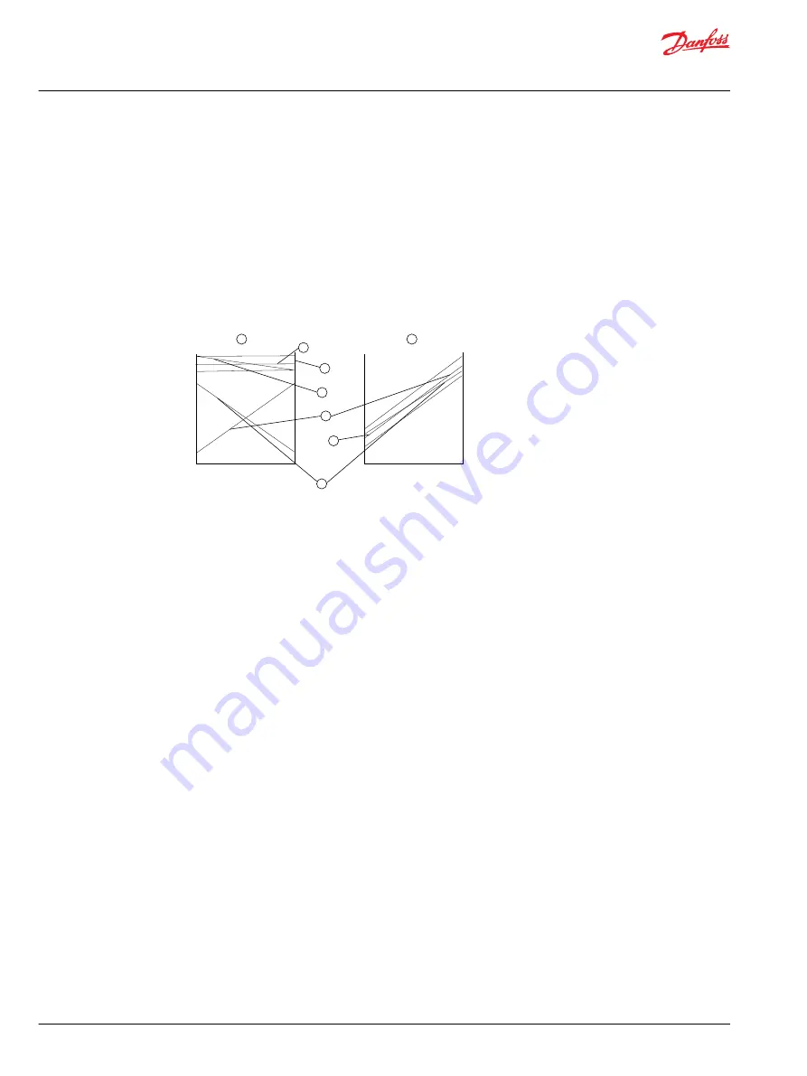
Output sense (direction)
The dual outputs from any JS2000 joystick can be configured in one of two possible ways. These are
designated within the joystick model code as
same sense
(P) or
opposite sense
(N). Refer to the following
Output sense (direction) diagram
for clarification.
The slopes at the lower end start at 20% of supply voltage range (Vs) and at the upper end finish at 80%
of Vs.
In the
same sense
configuration, the outputs of an axis can be directly compared to determine the
serviceability of the joystick. In the opposite sense configuration, the sum of the outputs from any axis
should be equal to the applied voltage.
Output sense (direction) diagram
kwa1392485224960
1
2
3
4
5
6
8
7
1
Oposite sense
5
Sum of outputs 1 and 2
2
Same sense
6
Output 1
3
Maximum difference sum to
supply voltage
7
Maximum difference between output 1 and 2
4
Supply voltage
8
Output 2
Dual JS2000 output signals (X and XY options)
Each joystick axis is equipped with two outputs and it is recommended that both outputs are
continuously compared to ensure that the difference does not exceed the maximum specified difference
plus an appropriate safety margin. In addition, machine movement should not be enabled until both
outputs from any one axis exceed the center threshold voltage plus a suitable safety margin (for example
twice the joystick center deadband).
The outputs in normal use should be within the limits 0.35 to 4.65 V DC. Any output significantly outside
of this range must be regarded as erroneous and appropriate safe action taken. A high value pull-up or
pull-down resistance should be added to the X and Y outputs such that in the unlikely event of a wire or
connector failure, the output will be pulled out of range.
Single outputs (XYZ option)
Where a joystick incorporating only a single sensor per axis is used to control safety critical functions, an
independent momentary action system enable switch should be provided.
Center tap
A center tap is provided as a means of verifying the integrity of the Vs at the joystick. Clearly a high
resistance or open circuit in either the Vs or ground connections will affect the joystick outputs. The
normal output at the center tap connection is 49.16 to 50.84% of Vs. A center tap output outside this
range indicates a fault in the supply to the joystick Hall sensors.
Technical Information
JS2000 Joystick
Product configuration model code
8 |
©
Danfoss | May 2017
520L0876 | BC00000073en-US0102