3
3.0 Installation instructions
The system should be installed by a competent person in the following
sequence.
3.1 Base unit
Install the base unit first. Mount the base unit above the distribution manifold
either direct on the wall or inside a wooden or metal distribution cabinet.
Ensure that the base unit is mounted horizontally, that there is easy access
to the control panel and thermal actuator connections, and that the base
unit cover can be easily removed. Fix the base unit to the wall using two
screws.
The base unit must be connected to a 230 volt supply via a double pole switch
socket outlet. If it is installed in a metal distribution cabinet, an aerial should
be installed outside the cabinet in order to improve radio communication.
3.2 Thermostat installation
Thermostats should be mounted on an internal wall at a height of 1.2-1.5
metres above the floor, using screws and fixings.
Thermostats must not be placed on an external wall or near heat sources
such as television and stereo sets, ovens or similar. Thermostats should not
normally be placed where they can be affected by direct sunshine. In rooms
that are very humid or damp, e.g. bathrooms, thermostats must be placed
as far from moisture sources as possible.
3.3 Pre-installation
Thermostats must be registered in the base unit before being placed in
individual rooms.
When registering thermostats, it is important that the room in which they are
to be placed is written or marked on the rear of the thermostat. Thermostats
can then be registered in turn.
The channels to be used for individual rooms must therefore be decided
in advance.
Note:
refer to section 4.3 for registration instructions
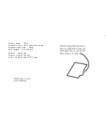
Fig. 2a. Thermostat location
Fig. 2b. Thermostat installation
4.0 Operating instructions
4.1 Thermal actuator installation
1.
Ensure that the power supply to the base unit is disconnected.
2.
Lift base unit cover after loosening front screws.
3.
Remove internal aerial.
4.
Remove blue thermal actuator terminals from printed circuit
board.
5.
Connect thermal actuator cables.
6.
Reattach thermal actuator terminals in assigned order to printed circuit
board.
7.
Position cables in strain-relief cable glands (see Fig 3).
8.
Replace internal aerial.
9.
Close base unit and tighten front screws
Fig. 3. Push cable through cable gland.
4.2 Base unit installation
Once the base unit has been mounted on the wall, all thermal actuators
have been connected and any connections for pump and boiler control
have been made, the thermostats can be registered. First, power up the
base unit. The green ‘Power’ LED lights up.
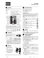
Fig. 4. Control panel. LED indicators 1-8 and ‘Power’ LED.
Ca. 1,5m
Power
1 2 3 4 5 6 7 8
Mode
OK


