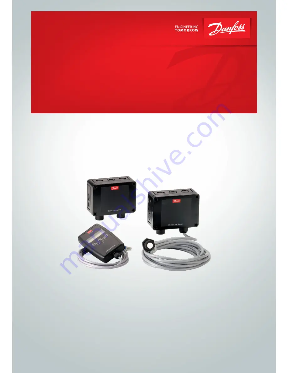
Danfoss Gas Sensor
Type DGS
Modbus or Service Tool display operation
User Guide
danfoss.com
Page 1: ...Danfoss Gas Sensor Type DGS Modbus or Service Tool display operation User Guide danfoss com ...
Page 2: ...nguage 12 4 5 3 LCD Function Check 12 4 6 Measuring Point Parameters 12 4 6 1 Alarm limits 12 4 6 2 Alarm delay 12 4 7 Menu System Parameters 13 4 7 1 AO function 13 4 8 Operating data 14 4 9 Calibration 15 4 9 1 Zero Calibration 16 4 9 2 Gain Calibration 17 4 9 3 Zero point calibration of Analog output 18 4 10 Addressing 18 5 Modbus menu survey 19 6 Technician use only 22 6 1 Regular test 22 6 2 ...
Page 3: ...User Guide Danfoss Gas sensor Type DGS Modbus or Service Tool display operation Danfoss DCS ADAP KOOL 2018 12 RS8KD102 3 ...
Page 4: ...me features described here are not possible and therefore the menu items may be hidden Some features are available from Modbus or handheld Service Tool interface only Differences is highlighted in this document 3 Operation The configuration and service is made via the handheld Service Tool or in combination with the Modbus interface Security is provided via password protection against unauthorized...
Page 5: ...ate is changed to 19 200 Baud Removing the jumper is required for integrating with Danfoss System Managers AK SM 720 and AK SM 350 Jumper 5 JP5 located on the top left is used to configure the analogue output type As default this is Voltage output By removing the jumper this is change to Current output Note the DGS must be power cycled before any change to JP4 take effect JP5 5 4 2 1 not used GND ...
Page 6: ...ce message Yellow Continuous Failure Slowly flashing Warming up Fast flashing Special mode Red Alarm The backlight of the display changes from green to red when an alarm is active 3 2 Setting changing of parameters and set points Open desired menu window Code input field opens automatically if no code is approved Set the desired parameter set point with the keys After input of valid code the curso...
Page 7: ... operation is done via a clear intuitive and logical menu structure The operating menu contains the following levels Starting menu with indication of the device type if no Measuring Point is registered otherwise scrolling display of the gas concentrations of all registered sensors in 5 second intervals If alarms are active only the values of the sensors currently in alarm status are displayed Main...
Page 8: ...Calibration Reading and acknowledgement of errors See chapter 4 1 Display of the status of active alarms See chapter 4 2 Display of the relay status Protected by password See chapter 4 3 Display of measuring values See chapter 4 4 Read out of handheld tool version language and set up of language Partly protected by password See chapter 4 5 Reading and change of the relay measuring point and system...
Page 9: ...eters System Parameters See chapter 4 6 See chapter 4 7 The following menu items are only accessible with Service ON password protected Service ON Special mode Fault message is active 4 Menu Overview Continued Starting menu Main menu Chapter Operating Data See chapter 4 8 MP Parameters See chapter 4 9 Calibration Addressing See chapter 4 10 ...
Page 10: ...3 Relay 3 Critical relay A1 A1 Alarm status A1 Alarm 1 active A1 Alarm 1 in latching mode can be acknowledged 4 3 Relay Status Reading of the current status of alarm relays The actual relay status is displayed depending on the relay mode energized de energized Selection of the alarm relay 1 X Alarm Relay Status Alarm Relay 1 Status OFF Symbol Description Function 1 Alarm Relay Alarm relay 1 X OFF ...
Page 11: ... exceeded ConfigError Gas type or meas range doesn t agree with sensor head Comm err Fault Measuring Point Communication error sensor head I O board Underrange Overrange Meas range monitoring Meas signal admissible range zero point 6 Meas signal admissible range full scale value 6 Locked Measuring Point locked Measuring Point was temporarily locked by the operator Warm up Warm up time Warm up time...
Page 12: ...rameters for each measuring point MP Parameters MP 1 Active Selection of measuring point 1 X Symbol Description Default Function 0 sec Delay Alarm 0 sec Gas concentration alarm threshold set time Alarm ON Gas concentration alarm threshold hysteresis Alarm OFF Warning limit C 5000 ppm 4 6 1 Alarm limits For each measuring point two alarm thresholds are available for free definition If the gas conce...
Page 13: ...ion of minimum output signal 0 V 0V at the minimum measuring signal of the sensor the output will be set to 0V 0mA without JP5 mounted 2V at the minimum measuring signal of the sensor the output will be set to 2V 4mA without JP5 mounted 4 7 1 AO Function The configuration of the analog outputs The analog output checks the current signal for validity Signal deviations of more than 5 from the nomina...
Page 14: ...n days of a new measuring point Days of Operation X Days Current days of operation Min Temperature 25 C Display of the lowest temperature detected at the device Max Temperature 25 C Display of the highest temperature detected at the device Maintenance Days remaining XXXX Days until the next calibration is due Operating Days last XXX Days of operation when the last calibration happened If more than...
Page 15: ...overview of the calibration menu The calibration description can be found on the following pages For HFC remember to use the specified calibration gas HFC grp1 R1234yf grp 2 R134a grp 3 R407c Calibrate Set the test gas concentraion Gain DP 1 Gain calibration Burn clean Selection of the measuring point to be calibrated Calibration AO 1 Only available for combustible gases Propane See section 4 9 1 ...
Page 16: ... When the current value is stable press for finishing the calculation of the new value Zero DP 1 0 ppm The display automatically goes to step 1 Display of new zero point Message Description Current value too high Wrong gas for zero point calibration Current value unstable Appears when the sensor signal does not reach the zero point within the target time Disappears automatically when the sensor si...
Page 17: ... automatically goes to step 1 Display Message Description Current value too high Test gas concentration than set value Internal error Replace sensor head Current value too low No test gas or wrong test gas applied to the sensor Test gas too high Test gas too low The set test gas concentration must be between 30 and 90 of the measuring range Current value unstable Appears when the sensor signal doe...
Page 18: ...ring range 20 mA DC to the analog output only after having opened the menu Calibration AO 1 Connect amperemeter to the analog output Calibration AO 1 320 323 Adjust the zero offset on the right by changing the offset value slowly until the amperemeter shows the desired value Display of the current zero offset on the left Calibration AO 1 SAVE Save the adjusted zero offset Calibration AO 1 323 323 ...
Page 19: ...rning alarm delay in seconds if set to 0 no delay 0 600 0 sec Alarm delay s When set to 1 the audible sounder are reset and the relays if defined Relay rest enable to no alarm indication When the alarm is reset or the time out duration is exceeded the value is reset to 0 Note The alarm condition is not reset only the output indication is reset 0 Alarm outputs not reset 1 Alarm outputs reset buzzer...
Page 20: ...ve Warning Coil under Power 0 1 0 Warning Relay Status of the buzzer 0 inactive 1 active 0 1 0 Buzzer Gas 2 Days until next calibration 0 32000 HFC 365 CO2 1825 R290 182 days 2 Days til calib Gas 2 Shows how many of Sensitivity remaining Note Value only updated after calibration 0 100 100 2 Rem sensivity Activates a mode which simulates an alarm Buzzer LED and relays all activate 1 Test function n...
Page 21: ...ibited Critical Limit alarm 0 Alarm not active 1 Alarm gas limit exceeded and delay expired 0 1 0 2 Criti limit 0 OK 1 Fault Out of range under test Overrange or Underrange 0 1 0 2 Out of range 0 OK sensor no errors 1 Fault Sensor and Head failures 0 1 0 2 Wrong SensType 0 OK sensor in place 1 Fault Sensor out or removed or wrong sensor placed in 0 1 0 2 Sens removed 0 OK Sensor not due for calibr...
Page 22: ...est Please observe that DGS works as a safety device securing a reaction to a detected high gas concentration If a leakage occurs the DGS will provide alarm functions but it will not solve or take care of the leakage root cause itself 6 2 Location For all gas heavier than air Danfoss recommends locating the sensor head app 30cm 12 above the floor and if possible in the air flow All gas measured wi...
Page 23: ...are 080Z2813 DGS IR CO2 5 m 080Z2801 Spare sensor CO2 5 m Spare 080Z2814 DGS IR 2 CO2 5 m 080Z2802 Hand Held Service Tool Accessory 080Z2820 DGS SC HFC gr 1 B L 080Z2809 Strobe Horn Accessory 080Z2819 DGS SC HFC gr 2 B L 080Z2810 Splash guard Accessory 148H6226 DGS SC HFC gr 3 B L 080Z2811 Duct set Accessory 148H6236 DGS PE Propane B L 080Z2812 Calibraton adaptor for SC2 Accessory 148H6232 DGS IR ...
Page 24: ...24 RS8KD102 Danfoss DCS ADAP KOOL 2018 12 ...