background image

Operation

The purpose of this section is to indicate the necessary procedures to perform the pump start up.

Pre-start up controls for D1P pump
Before performing the first pump start up, the following points have to be checked.

Hydraulic components must be installed in accordance with their individual instruction.

1. To avoid contamination, plastic plugs in connection ports must not be removed until just before

connections are made.

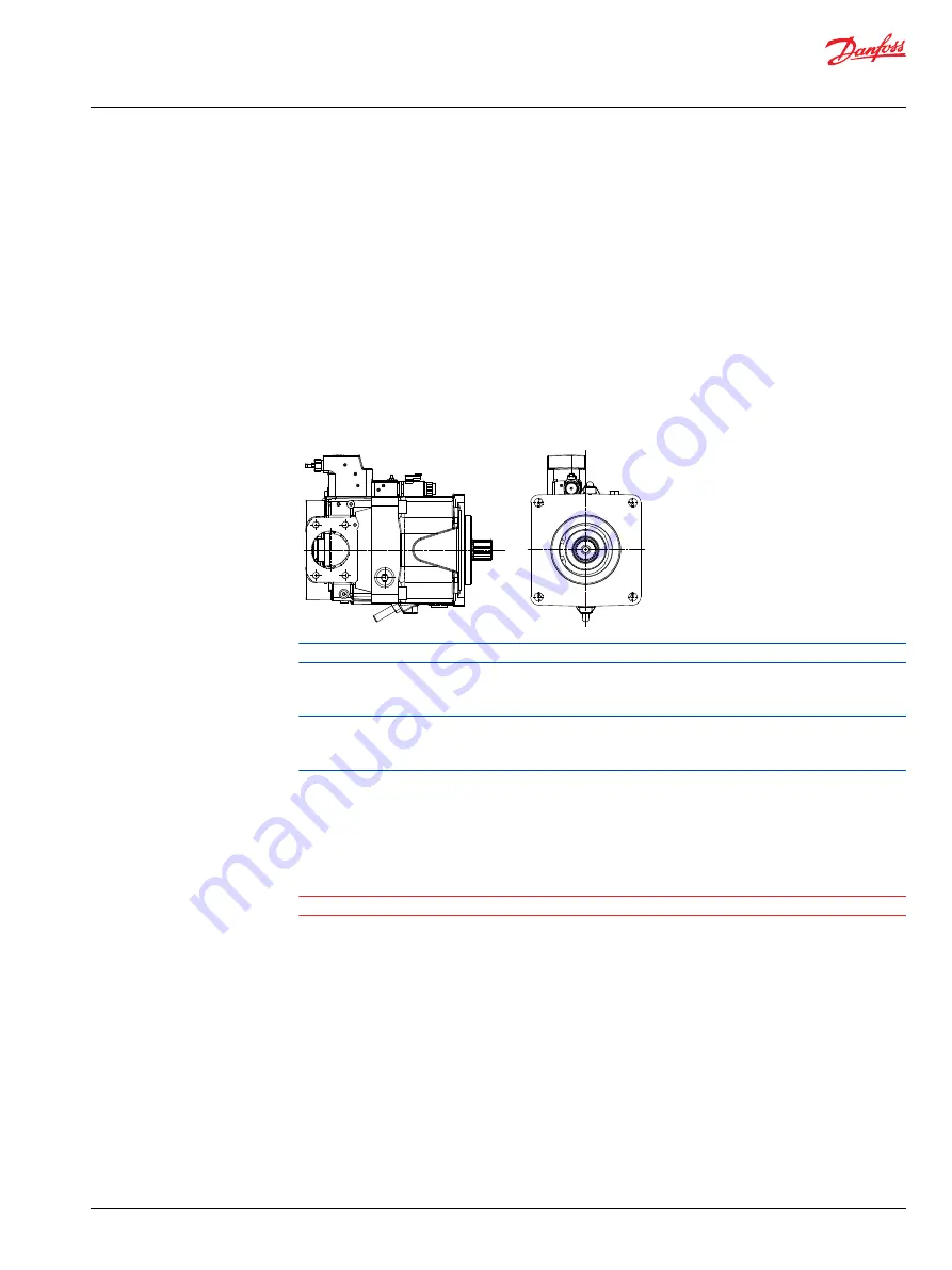
2. Make sure the pump hydraulic connections allow the pump to rotate in the desired direction. For

pumps with standard direction of rotation:

Clockwise rotation (viewed facing the output shaft) with inlet pressure in the front port.

Counter-clockwise rotation (viewed facing the output shaft) with inlet pressure in the rear port.

Generic illustration shown.

3. Select the hydraulic fluid as specified in 

Oil types / Operating fluids

.

4. Ensure full contact between pump mounting flange and connecting part.

Avoid pressing the pump into place by tightening the fixing bolts. Avoid unsuitable seal materials, for

example, twine and Teflon, on threaded unions. Use only the seals supplied, such as O-rings, steel

washers.

5. Make sure that all couplings are completely tightened to prevent leakage.

Do not use more torque than the maximum values given in the instructions.

6. Check to make sure the purity of the oil is greater than 22/20/16 (ISO 4406-1999) and always use a

filter when replenishing the system.

W

Warning

The pump must be filled with fluid prior to any load applications.

User Manual

ATEX certified D1P 130/145/193/260

Installation, operation and maintenance


©

 Danfoss | August 2021

BC376161003883en-000101 | 11

Summary of Contents for D1P130

Page 1: ...User Manual ATEX certified Axial piston pump variable displacement D1P130 D1P145 193 260 www danfoss com...

Page 2: ...Revision history Table of revisions Date Changed Rev August 2021 First edition 0101 User Manual ATEX certified D1P 130 145 193 260 2 Danfoss August 2021 BC376161003883en 000101...

Page 3: ...ting fluids 7 Viscosity and temperature for D1P pump 8 Ambient temperature 8 Oil temperature 8 Viscosity 8 Filtering 9 Installation operation and maintenance Assembly of D1 pump to the system 10 Opera...

Page 4: ...afety The safety of the product depends upon the strict observation of the indications given in this User Manual in particular it is necessary to Always operate within allowed product working operatin...

Page 5: ...Ex II 3G Ex h IIA T3 Gc AN3 temperature class T3 CE Ex II 3G Ex h IIA T4 Gc AN4 temperature class T4 CE Ex II 3G Ex h IIA T5 Gc AN5 temperature class T5 See Viscosity and temperature for D1P pump on p...

Page 6: ...ly explosive atmospheres With following parameters Equipment group II Zone 2 gas Equipment Category 3G Temperature class T5 T3 Explosion protection group II A The Conformity Assessment Procedure has t...

Page 7: ...40 F T5 T4 T4 80 C 176 F T4 T4 T3 115 C 239 F T3 T3 T3 T codes maximum surface temperature Temperature class Maximum surface temperature C F T3 200 392 T4 135 275 T5 100 212 To ensure that the surface...

Page 8: ...account by the safety margin to the minimum ignition temperature of the dust concerned For up to 5 mm 1 97 in layer thickness the safety margin is 75 C 167 F For further information please see IEC 600...

Page 9: ...t the actual operating temperature Filtering It is necessary to keep the level of oil contamination at an acceptable level to ensure problem free operation The recommended maximum level of contaminati...

Page 10: ...200 C for Group 11G Make sure that all type of accessory installed on the pump are ATEX specified and have been installed in accordance with ATEX requirements There are no creeping metal elements exte...

Page 11: ...shaft with inlet pressure in the rear port Generic illustration shown 3 Select the hydraulic fluid as specified in Oil types Operating fluids 4 Ensure full contact between pump mounting flange and con...

Page 12: ...eanliness level b Replace oil filter or change the hydraulic fluid if the required cleanliness level is not reached Operational checks The product is a component which requires no settings or changes...

Page 13: ...color bad smell acidity increase and because of the generation of sludge inside the tank In case symptoms of this kind are detected the system oil must be immediately changed Water presence The prese...

Page 14: ...ause injury to the technician or bystanders To protect against unintended movement secure the machine or disable disconnect the mechanism while servicing Follow the manufacturers instructions for secu...

Page 15: ...nfoss Power Solutions US Company 2800 East 13th Street Ames IA 50010 USA Phone 1 515 239 6000 Danfoss Power Solutions Trading Shanghai Co Ltd Building 22 No 1000 Jin Hai Rd Jin Qiao Pudong New Distric...

Reviews: