


2
Application guide RA8AB102 © Danfoss 10/2010
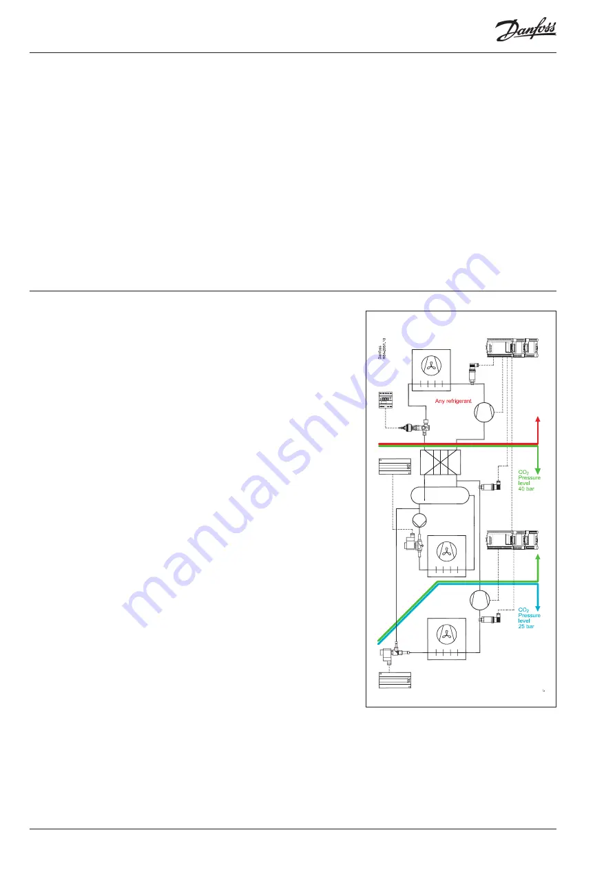
Cascade HC/HFC - CO2 system
Intermediate temperature in a cascade system is
selected based on the required temperature for
high temperature cases in a store which means
they can be cooled by CO2 directly. Intermediate
temperature can also be optimised for the high-
est energy efficiency if the system is used for low
temperature only.
Since a cascade system actually consists of two
different refrigeration systems which are inter-
faced but isolated at the cascade heat exchanger,
the design working pressure for each can be
different. CO2 design pressure is normally based
on the availability of components and is equal to
40-45 bar (corresponding to +5 - +10°C).
In order to prevent pressure from increasing
above the previously mentioned measurements,
standstill systems are recommended. Safety
valves should have the highest setting. Stand still
pressure can be achieved by raising the desing
pressure to 80-90 bar.
For example:
CO2 side
• System design working pressure (saturated suc-
tion temperature): 40 bar (+5°C)
• Safety valve settings: 36 bar (-10% MWP)
• System emergency relief setting: 34 bar (-1°C)
• CO2 discharge pressure setting: 30 bar (-5°C)
The higher the efficiency of the cascade heat
exchanger, the lower the difference between
the condensation temperature of CO2 and the
evaporating temperature of the refrigerant on
the high temperature side. As the temperature
difference on the cascade condenser increases,
the overall efficiency of the refrigeration system
decreases!
General description
Temperatures and pressures
in cascade systems
Ammonia/CO2 cascade systems have the highest
efficiency of all. If HFC is to be used at a high tem-
perature stage, R134a is a preferable option due
to its thermo dynamical properties and lower
(compared to R404A) GWP potential.
Cascade systems are typical not used in FR ap-
plications with traditional refrigerants. There are a
few reasons for this such as the need to maintain
two different refrigerants in one system; system
control strategy (especially that of a cascade heat
exchanger) is more complex. At the same time
using CO2 in cascade systems gives a number of
advantages:
• Efficiency of the system is high even in the hot
climates
• Only a small amount of refrigerant is needed for
high temperature stage
• Temperature difference for cascade heat ex-
changer is relatively low
• On the high side various refrigerants can be
used ex HC/HFC or NH3.
EKC 313
AK-CC 550
AK-CC 450
AK-PC 740/780
AK-PC 740/780