


Airflex
®
DBB 8110 Brake Assembly
E-CLCL-TT001-E December 2012
12
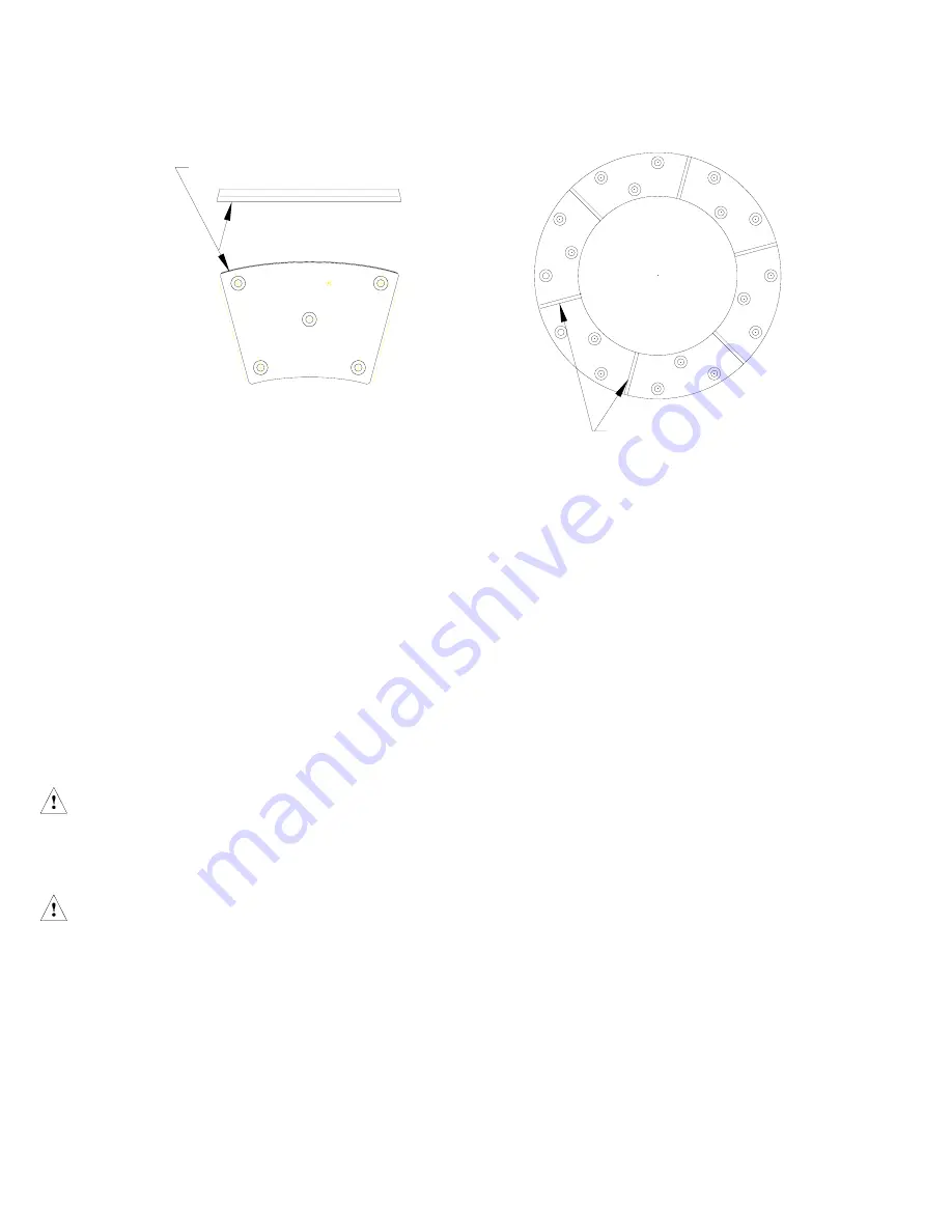
FRICTION BLOCK WEAR GROOVE
WEAR GROOVES
Figure 4
4.2.1
To determine when adjustment is required, make
sure the brake is engaged then measure the gap
between the spring housing (16) and the pressure
plate (14) as shown in Figure 5. Measure the ‘Y’ gap
between the pressure plate (14) and the reaction
plate (31), the ‘Y’ gap between the reaction plate (31)
and the mounting flange (2) and the ‘Y’ gap between
the reaction plates (31) as shown in Figure 5, 6,
7,
8 and 9. If the measured gaps meet or be outside
(larger or smaller) the limits shown on Table 8 AND
none of the friction discs are worn to the bottom
of the wear groove or the step on size 50 brakes,
adjust the brake. It is also recommended to check
the DBBS components for wear as shown in Table
7.
If any wear limit has been reached or exceeded, that
component must be repaired or replaced.
Warning
If a wear adjustment is not made, the brake torque
may deteriorate to the point where the equipment
will not stop properly.
Caution
Remove, retain or support discs as needed so that
they do not fall off the gear during maintenance.
Note
Prior to August 2012, multiple disc DBBS units were
manufactured with solid wear spacers (29), requiring
brakes to be fully disassembled in order to make
wear adjustments. Multiple disc units manufactured
from August 2012 and later, use the split wear
spacers and adjustment can be conducted without
full disassembly. Check the date code on your brake
to verify the date of manufacture.
4.2.2
Wear Adjustment with Solid Wear Spacers
Note
A Procedures for adjusting a two disc brake are listed
below as an example.
4.2.2.1 Disconnect the air supply lines from the brake. Wipe
down the brake and match mark all components
from the mounting flange (2) to the cylinder (19)
prior to disassembly. Match marking all components
will ensure that the components are reinstalled in
the orientation and location from which they were
removed.
4.2.2.2 While supporting the cylinder (19), loosen the
locknuts (18) ONE TURN AT A TIME and in an
alternating (crosswise) pattern to prevent binding
of the cylinder on the studs. Continue to loosen the
locknuts until the force of the release springs (34)
is relieved, allowing for access to the wear spacers
(29). It may be necessary to push the reaction
plate(s) (31) away from the mounting flange so that
the release springs can be moved to gain access to
the wear spacers.
Note
Once the assembly is loose, the wear spacers (29)
can be rotated to confirm that they are the ‘Solid
Wear Spacers’ and the disassembly can proceed per
4.2.2.3 below. The split spacers are identified by the
presence of a slot running across the thickness
of the spacer. If the wear spacers have the slot,
then they have been replaced with a split spacer kit
and the DBBS can be adjusted without complete
disassembly. See Section 4.2.3 for wear adjustment
with split wear spacers. See figure 11 for an
illustration of the split wear spacer.
DBBS Brakes
Summary of Contents for Airflex DBBS
Page 26: ......


