background image

70 

Heat pump controller    RS8GF202  ©  Danfoss  2015-08 

AK-HP 780

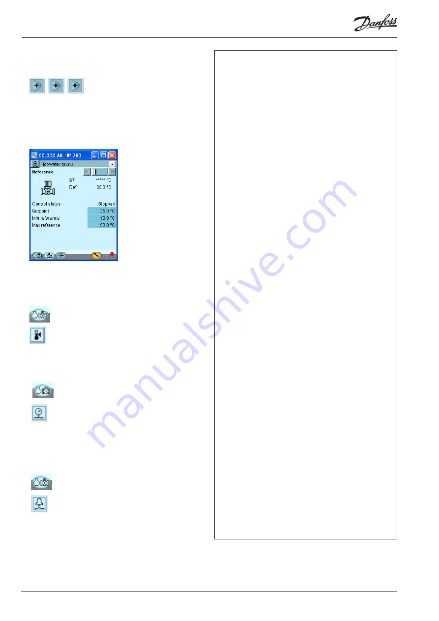
7. Move on through all the individual displays for the 

pump.  

Change displays with the +- button. Remember the settings at 
the bottom of the pages – the ones that can only be seen via 
the ”Scroll bar”.

8. Safety limits

9. Go back to the overview and Move on to the ther-

mostat group

Check the settings.

10. Go back to the overview and Move on to the press-

sostat group

Check the settings.

11. Go back to the overview and on to the general 

alarm inputs

Check the settings.

12. The controller setup has been completed.

Check of settings - continued

The last page contains reference settings

Summary of Contents for ADAP-KOOL AK-HP 780

Page 1: ...Heat pump controller with oil management AK HP 780 Design Guide ADAP KOOL Refrigeration control systems...

Page 2: ...n the basic module 39 Wiring 40 4 Configuration and operation 43 Configuration 45 Connect PC or PDA 45 Authorization 46 Unlock the configuration of the controllers 47 System setup 48 Set plant type 49...

Page 3: ...Either shared or individual for all of the com pressor s oil valves Receiver pressure control Speed control of one or two compressors Up to 6 safety inputs for each compressor Option for capacity limi...

Page 4: ...to be mounted If the system grows and more functions have to be controlled the regulation can be extended With extra modules more signals can be received and more relays cut in and out how many of th...

Page 5: ...n be linked up into a network together with other controllers in an ADAP KOOL refrigeration control system After the setup operation can be performed at a distance with say our software program type A...

Page 6: ...made real time and displayed instantly Alarm The display gives you an overview of all active alarms If you wish to confirm that you have seen the alarm you can cross it off in the acknowledge field If...

Page 7: ...t with a specific software and by which input and output signals the relevant application will require If it is an application with few connections the controller module top part with belonging bottom...

Page 8: ...xtension module with additional relay outputs and additional analog inputs The module with additional relay outputs is also available in a version where the top part is provided with change over switc...

Page 9: ...cable and AK controller Cable between PDA cable and AK controller AK RS 232 Accessories Power supply module 230 V 115 V to 24 V d c AK PS 075 18 VA Supply for controller AK PS 150 36 VA Accessories E...

Page 10: ...me output group Solid state outputs Can be used for loads that are cut in and out frequently e g Oil valves Max 240 V a c Min 48 V a c Max 0 5 A Leak 1 mA Max 1 AKV Ambient temperature During transpor...

Page 11: ...02 Danfoss 2015 08 11 Dimensions The module dimension is 72 mm Modules in the 100 series consist of one module Modules in the 200 series consist of two modules Controllers consist of three modules The...

Page 12: ...ting When the controller is connected to a gateway type AKA 245 the controller s address must be set between 1 and 119 If it is a system manager AK SM then 1 999 Service PIN When the controller is con...

Page 13: ...4 3 AI 3 5 6 4 AI 4 7 8 5 AI 5 9 10 6 AI 6 11 12 7 AI 7 13 14 8 AI 8 19 20 9 AI 9 21 22 10 AI 10 23 24 11 AI 11 25 26 12 DO 1 31 32 13 DO 2 33 34 14 DO 3 35 36 15 DO 4 37 38 16 DO 5 39 40 41 17 DO6 4...

Page 14: ...signals Supply voltage The supply voltage to the module comes from the previous module in the row Supply voltage to a pressure transmitter can be taken from either the 5 V output or the 12 V output d...

Page 15: ...S 32R AKS 32 P0 Pd Prec AKS 32R AKS 2050 1 xx bar AKS 32 1 zz bar U 0 5 V 0 10 V On Off Ext Main switch Day Night Level switch Active at Closed Open Point 5 6 7 8 Type AI5 AI6 AI7 AI8 Point 1 2 3 4 Ty...

Page 16: ...Function The module contains 8 inputs for on off voltage signals Signal AK XM 102A is for low voltage signals AK XM 102B is for high voltage signals Supply voltage The supply voltage to the module com...

Page 17: ...3 4 3 DI 3 5 6 4 DI 4 7 8 5 DI 5 9 10 6 DI 6 11 12 7 DI 7 13 14 8 DI 8 15 16 Point Signal Active at DI Ext Main switch Day Night Comp safety 1 Comp safety 2 Level switch Closed voltage on Open voltage...

Page 18: ...row Voltage supply to the controller Communication active with the bottom PC board red error Status of outputs DO1 to DO8 Right row AK XM 204B only Override of relays ON override OFF no override Fuse...

Page 19: ...Module Point Terminal Active at 1 DO 1 25 27 2 DO 2 28 30 3 DO 3 31 33 4 DO 4 34 36 5 DO 5 37 39 6 DO 6 40 41 42 7 DO 7 43 44 45 8 DO 8 46 47 48 Signal Active at DO Comp 1 Comp 2 Pump Alarm Solenoid...

Page 20: ...ion Auto the controller carries out the control Light emitting diodes There are two rows with LED s They mean Left row Voltage supply to the controller Communication active with the bottom PC board re...

Page 21: ...l Signal type S Pt 1000 ohm 0 C Sctrl S7 Saux1 Saux2 SS Sd Pt 1000 P AKS 32R AKS 32 P0 Pd Prec AKS 32R AKS 2050 1 xx bar AKS 32 1 zz bar U 0 5 V 0 10 V On Off Ext Main switch Day Night Level switch Ac...

Page 22: ...he module contains two analog voltage outputs of 0 10 V Supply voltage The supply voltage to the module comes from the controller module Placing The module is placed on the PC board in the controller...

Page 23: ...Fixed times for day night change over Saving of alarm log in case of power failure Saving of temperature log in case of power failure Connection The module is provided with plug connection Placing Th...

Page 24: ...ule is connected to the controller module via a cable with plug connections You have to use one cable per module The cable is supplied in various lengths Both types of display with or without control...

Page 25: ...ly for controller Supply voltage 230 V a c or 115 V a c from 100 V a c to 240 V a c Placing On DIN rail Effect Type Output tension Output current Power AK PS 075 24 V d c 0 75 A 18 VA AK PS 150 24 V d...

Page 26: ...er time and winter time are contained in the controller The clock is zeroset when there is power failure The clock s setting is maintained if the controller is linked up in a network with a gateway a...

Page 27: ...ound on the controller module When programming the function must be set Active when the output is activated Active when the output is not activated Analog output signal AO This signal is to be used if...

Page 28: ...s each compressor 3 Identical compressor capacities x Different compressor capacities x Sequential operation first in last out x Speed regulation of 1 compressor or 2 parallel compressors x Run time e...

Page 29: ...t the functions go to chapter 5 Connections Here is a survey of the possible connections The texts can be read in context with the table on page 31 Analog inputs Temperature sensors Sctrl Must always...

Page 30: ...of one Safety monitoring of each compressor Common high pressure monitoring Sctrl setting 60 C Night setback of 5 K Oil management of each compressor Pulse reset for stopped compressor lack of oil Rec...

Page 31: ...each compressor 4 Safety circuits flow switch for the pump Max 1 fan Safety circuits frequency converter External start stop 1 Night setback Sctrl temperature Separate alarm functions via DI 1 Load sh...

Page 32: ...will all the time check whether there is connection to the connected modules This status can be followed by the light emitting diode When the two catches for the DIN rail mounting are in open positio...

Page 33: ...7 AI 7 13 14 AKS 2050 159 Level switch oil comp 1 8 AI 8 19 20 Closed Level switch oil comp 2 9 AI 9 21 22 Closed Level switch oil comp 3 10 AI 10 23 24 Closed Level switch oil comp 4 11 AI 11 25 26...

Page 34: ...er level Reset oil manage ment Room fan Connection diagram Drawings of the individual modules may be ordered from Danfoss Format dwg and dxf You may then yourself write the module number in the circle...

Page 35: ...V must not be shared by other controllers or units The analog inputs and outputs are not galvanically separated from the supply The and 24V input must not be earthed Transformer size The power consum...

Page 36: ...able between zero modem cable and AK controller Cable between PDA cable and AK controller AK RS 232 080Z0261 Accessories Power supply module 230 V 115 V to 24 V d c AK PS 075 18 VA Supply for controll...

Page 37: ...ction describes how the controller Is fitted Is connected We have decided to work on the basis of the example we went through previously i e the following modules AK HP 780 controller module AK XM 205...

Page 38: ...o voltage Press in the plate on the left hand side of the light emitting diodes and the plate on the right hand side for the red address changers Lift the top part off the basic module 2 Mount the ext...

Page 39: ...basic module must not be connected to voltage Mounting and wiring continued When the two snap catches for the DIN rail mounting are in the open position the module can be pushed into place on the DIN...

Page 40: ...O 1 31 32 ON Solenoid valve oil Comp 2 13 DO 2 33 34 ON Solenoid valve oil Comp 3 14 DO 3 35 36 ON Solenoid valve oil Comp 4 15 DO 4 37 38 ON Solenoid valve oil Receiver 16 DO 5 39 40 41 ON 17 DO6 42...

Page 41: ...5 08 41 Mounting and wiring continued Warning Keep signal cables separate from cables with high voltage The screen on the pressure transmit ter cables must only be connected at the end of the controll...

Page 42: ...controller will be ready in just under one minute when the light emitting diode Status starts flashing slowly 5 When there is a network Set the address and activate the Service Pin 6 The controller is...

Page 43: ...guration and operation This section describes how the controller Is configured Is operated We have decided to work on the basis of the example we went through previously i e compressor control with 4...

Page 44: ...or oil shortage Pump Pump with speed control S7 setting 40 C Receiver Monitoring of liquid level of refrigerant Control of pressure in oil receiver Fan in plant room Thermostat control of fan in engin...

Page 45: ...roller an overview of it will always appear In this case the overview is empty This is because the controller has not yet been set up The red alarm bell at the bottom right tells you that there is an...

Page 46: ...ne with the user name SUPV Press the button Change When the controller is supplied it has been set with standard authoriza tion for different user interfaces This setting should be changed and adapted...

Page 47: ...ct Lock Unlock configuration 3 Select Configuration lock Press the blue field with the text Locked 4 Select Unlocked Select Unlocked and press OK Configuration continued The controller can only be con...

Page 48: ...g in the blue field with the setting and then indicating the value of the required setting In the first field you enter a name for what the controller will be control ling When the time is set the PC...

Page 49: ...settings can be entered on the following pages In the example we select this set up mode to get through the descrip tions of the functions Here you can make a choice between a number of prede fined co...

Page 50: ...r information Step control mode Select coupling pattern for compressors Sequential Compressors are cut in out in strict ac cordance with compressor number FILO Cyclic Runtime equalisation between comp...

Page 51: ...ariable speed drive the nominal capacity must be set for the mains frequency 50 60 Hz Unloader Number of unload valves for each compressor 0 3 6 Capacity distribution The installation is dependent on...

Page 52: ...ssure etc Define here whether this type of protection should be con nected For General there is a signal from each compressor 9 Minimum operation times Configure the operation times here so unnecessar...

Page 53: ...f a lack of oil is registered when the compressor is force controlled Forced con trolled to ON with the setting Manual or with the changeover on an extension module Danfoss recommends this function to...

Page 54: ...r is to be controlled separately Oil cycle pre delay Prel period Oil pulses will start after a stable signal from the level switch in the entire delay time Oil cycle post delay Prel period Oil pulses...

Page 55: ...peed The pump is controlled via speed control frequency converter Control type Choice of control strategy P band The pump capacity is regulated via P band control The P band is configured as Proportio...

Page 56: ...to be shown for the individual outputs In our example separate displays are not used The setting is included here for information 3 Display setup Display The following can be read for the four outputs...

Page 57: ...ons In our example we select one alarm function for monitoring the liquid level in the receiver We have subsequently selected a name for the alarm function and for the alarm text 3 General alarm input...

Page 58: ...perature sensors Each thermostat has a separate outlet to control external automa tion No of thermostats Set the number of general thermostats For each thermostat adjust Name Which of the sensors is u...

Page 59: ...his relay if all you require is an alarm message via the data communication Setup separate voltage functions 3 Voltage inputs The general volt inlet can be used to monitor external voltage signals Eac...

Page 60: ...ction is to be ac tive when the output is in pos Closed or Open Open has been selected here for all the safety circuits This means that the controller will receive signal under normal operation and re...

Page 61: ...bar AKS 2050 1 99 bar AKS 2050 1 159 bar User defined only ratiometric min and max value of the pressure range must be set Sctrl compressor control Po suction pres Ss suction gas Sd disch gas temp Pd...

Page 62: ...t alarms that are current They will be shown with text in the three pictures All alarms that can occur can be set for a given order of priority High is the most important one Log only has lowest prior...

Page 63: ...ler RS8GF202 Danfoss 2015 08 63 Press the button to go on to the next page 5 Set alarm priorities for thermostat and extra digital signals Configuration continued In our example we select the settings...

Page 64: ...comparison of selected func tions and define inputs and outputs The result can be seen in the next section where the setup is controlled Configuration continued Press in the field against Configuratio...

Page 65: ...umber and point number that does not exist The selected point number on the selected mod ule had been set up for something different The error is corrected by setting up the output correctly Remember...

Page 66: ...utputs Press the button to go on to the next page 6 Check configuration of Analog Inputs Configuration continued The setup of the analog outputs appears as it is supposed to according to the wiring ma...

Page 67: ...ted as expected This controls requires that the setup is locked By means of the manual control of each output it can be checked whether the output has been correctly connected Cut out the safety circu...

Page 68: ...le values In our case we have no values This may be due to the following The sensor has not been connected The sensor is short circuited The point or module number has not been set up correctly The co...

Page 69: ...f the pages the ones that can only be seen via the Scroll bar 4 Safety limits 5 Go back to the overview 6 Select the pump Before the control starts we check that all the settings are as they should be...

Page 70: ...can only be seen via the Scroll bar 8 Safety limits 9 Go back to the overview and Move on to the ther mostat group Check the settings 10 Go back to the overview and Move on to the press sostat group...

Page 71: ...he schedule function for the night setback of the reference In other cases where the controller is installed in a network with one system unit this setting may be made in the system unit which will th...

Page 72: ...t 3 The arrow of the two other address switches must point at 0 2 Push the Service Pin Press down the service pin and keep it down until the Service Pin LED lights up 3 Wait for answer from the system...

Page 73: ...ist Press the red cross to remove cancelled alarms from the alarm list 5 Check active alarm again In our case we have a series of alarms We will tidy them up so that we only have those that are releva...

Page 74: ...lue manual control button at the bottom of the display 2 Start control First start of control continued Press in the field against Main switch Select ON Press OK The controller will now start controll...

Page 75: ...y in percent Press in the blue field against Manual capacity If you need to manually adjust the capacity of the compressors you can use the following procedure WARNING If you force control the compres...

Page 76: ...76 Heat pump controller RS8GF202 Danfoss 2015 08 AK HP 780...

Page 77: ...AK HP 780 Heat pump controller RS8GF202 Danfoss 2015 08 77 5 Regulating functions This section describes how the different functions work...

Page 78: ...y function for low suction pressure and will ensure disconnection of compressor capacity Handling of sensor error In the event of an error in the Sctrl sensor regulation will continue by the P0 signal...

Page 79: ...reference a limitation of the reference must be set Forced operation of the compressor capacity in the suction group A forced operation of the capacity can be carried out which disregards the normal...

Page 80: ...uested compressor capacity by the PI controller The rate of change in the requested capacity depends upon in which zone the pressure is and whether the pressure is stable or whether it is constantly c...

Page 81: ...l be activated The amplitude of the zone extension will be highest when Minimize number of couplings is set to High Please refer to the next sketch which shows an example with 6 compressor steps and w...

Page 82: ...g on the restart timer or is safety cut out this step is replaced by another compressor Operating time equalisation The operating hour equalizing is carried out between compressors of the same type wi...

Page 83: ...pressors 4 When two speed regulated compressors are used they must have the same frequency range For cyclical coupling patterns the two speed regulated compressors should be the same size and the subs...

Page 84: ...is now up to the frequency converter to bring the speed up to Start speed The capacity step will now be cut in and the required capacity determined by the controller The start speed always ought to b...

Page 85: ...ollowing compressor steps If the variable part of the speed controlled compressor is smaller than the following compressors there will be holes in the capacity curve Example 1 speed controlled compres...

Page 86: ...uent speed regulated compressor will be cut in when the first compressor runs at max speed and the desired capacity has reached a value that allows the cut in of the next speed regulated compressor at...

Page 87: ...d regulated compressors with a nominal capacity of 10 kW and 20 kW respectively Frequency range of 25 60 Hz Two one step compressors of 20 and 40 kW respectively Load shedding On some installations th...

Page 88: ...tely cut out The alarm is cancelled and renewed cutin of compressor steps is permitted when the following conditions are met the temperature has dropped to 10 K below the limit value the time delay pr...

Page 89: ...n of compressor steps is permitted when the following conditions are met the temperature pressure falls to 3 K below the limit value the time delay for restart has been passed Delay of Pd max alarms I...

Page 90: ...r can also be used to control but this is not energy efficient Examples of oil circuits Control principle for compressor A compressor that is shut down does not receive any oil When the compressor is...

Page 91: ...ed manually in the plant itself This can be done via a pulse pressure on a defined input There is one reset and this applies to all compressors Upon reset all the counters are reset Control principle...

Page 92: ...rature and the reference value The proportional band Xp indicates the deviation at 100 condenser capacity Regulating sensor S7 is used as a regulating sensor The set point for the S7 temperature is se...

Page 93: ...of plant pressure or for ON OFF pressure control regulation The pressure control can either use one of the sensors used by the control function Po Pc or an independent sensor Paux1 Paux2 Paux3 Cutin a...

Page 94: ...orrected A correction will only be necessary if the sensor cable is long and has a small cross sectional area All displays and functions will reflect the corrected value Clock function The controller...

Page 95: ...ntations The log only works when the clock has been set Forced operation via network The controller contains settings that can be operated from the gateway s forced operation function via data communi...

Page 96: ...al reference temperature for compressor capacity r28 Set point S7 ISetting of required temperatures in C r29 S7 reference Actual reference for temperature regulation r57 Po evaporating pressure in C u...

Page 97: ...bination is that the unloader valves will be used to fill in capacity gaps and thereby achieve many capacity steps via few compressors Preconditions for using this compressor application are All compr...

Page 98: ...ity regulated compressor is used to fill capacity gaps Operating hours are equalised between the one step compres sors 3 and 4 Compressor application 4 Only capacity controlled compres sors The contro...

Page 99: ...nt to the capacity of the cut in capacity Decreasing capacity The small one step compressor is cut out when the speed regu lated compressor has reached minimum speed 30 Hz When the speed regulated com...

Page 100: ...pling pattern The same frequency band for both speed regulated compressors One step compressors of the same or different sizes depending on the choice of coupling pattern This compressor combination c...

Page 101: ...e one step compressors are cut out the speed regulat ed compressors speed increases 63 3 Hz equivalent to the cut out capacity Example 2 In this example the speed regulated compressors are of differen...

Page 102: ...ave been cut out on common safety input Comp 1 safety Comp 2 safety Comp 3 safety _________________ Comp 12 safety Medium Comp X oil pressure cut out Compressor no x has been cut out on oil pressure s...

Page 103: ...m input Low Custom alarm x define text Alarm on general alarm input DI x System alarms The alarm priority can not be altered on system alarms Control mode Low Manual comp cap Control A Compressors cap...

Page 104: ...check the installation thoroughly and to fit the necessary safety devices Special reference is made to the necessity of signals to the controller when the compressor is stopped and to the need of liqu...

Reviews: