MAKING MODERN LIVING POSSIBLE
Repair Instructions
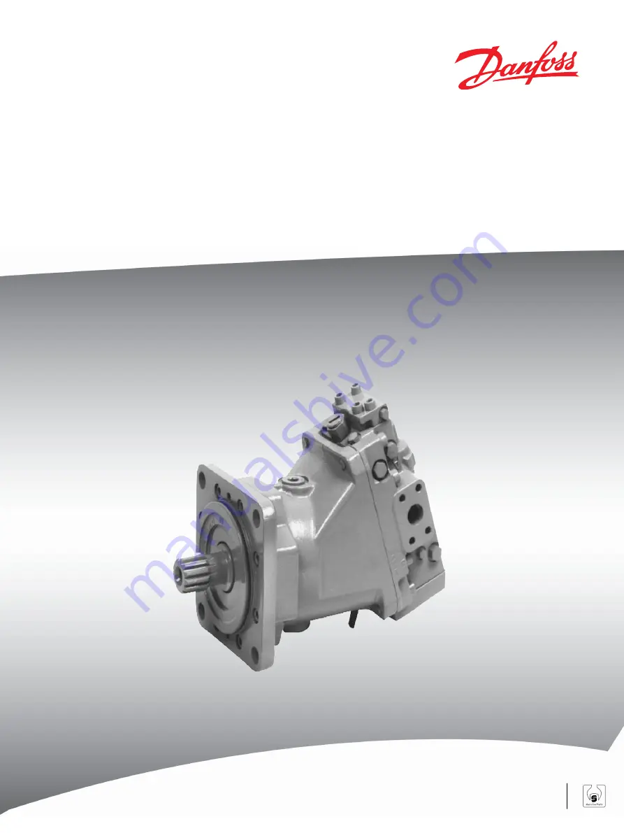
Bent Axis Motors
Series 51 and 51-1 Repair
Instructions
powersolutions.danfoss.com
Page 1: ...MAKING MODERN LIVING POSSIBLE Repair Instructions Bent Axis Motors Series 51 and 51 1 Repair Instructions powersolutions danfoss com...
Page 2: ...history Table of revisions Date Changed Rev December 2014 Danfoss layout BA Jan 2008 First edition AA Repair Instructions Series 51 and 51 1 Bent Axis Motors Repair Instructions 2 11009449 Rev BA Dece...
Page 3: ...y 12 060 frame 12 080 frame 13 110 250 frame 13 All frame sizes 14 51 1 Endcap 14 Inspection Shaft assembly 16 Piston rings 16 Bearing plate valve segment and cylinder block 17 Assembly Endcap assembl...
Page 4: ...erforming major repairs remove the unit from the vehicle machine Chock the wheels on the vehicle or lock the mechanism to inhibit movement Be aware that hydraulic fluid may be under high pressure and...
Page 5: ...ents are flammable To avoid possible fire do not use cleaning solvents in an area where a source of ignition may be present Fluid under pressure W Warning Escaping hydraulic fluid under pressure can h...
Page 6: ...orientation for reinstallation Parallelism specification Torque specification External hex head Press in press fit Internal hex head Pull out with tool press fit Torx head Cover splines with installa...
Page 7: ...Tapered roller bearings Bearing plate Valve segment Control hydraulic proportional Minimum displacement limiter Motor output shaft Housing Minimum angle servo cover End cap Control springs 4 way valve...
Page 8: ...discard 4 Remove the alignment pins B50 Endcap and rotating components Q20 G60 B50 C05 G34 B50 C20 SAE flange version Cartridge version G32 End cap assembly side port configuration shown Note orienta...
Page 9: ...ly side port configuration shown Note orientation of rollers with synchronizing shaft recess faces the centerline of the shaft later version rollers do not have recess and can be installed either way...
Page 10: ...bly SAE or DIN flange version L70 L35 L50 B10 Shaft assembly 060 and 080 6mm 110 8mm 160 10mm 250 12mm P104 087 L40 Repair Instructions Series 51 and 51 1 Bent Axis Motors Repair Instructions Disassem...
Page 11: ...removal Cartridge 1 Remove retaining ring L80 2 Remove seal carrier L750 3 Remove shaft seal L40 discard 4 Remove retaining ring L80 for the shaft seal carrier L750 from the bearing housing L35 5 Rem...
Page 12: ...0 L80 L750 L35 L95 L81 N98 33 and beyond P104 088 060 and 080 6mm 110 8mm 160 10mm 250 12mm Endcap disassembly 060 frame 1 Remove end cap plug G80 Remove O ring G80A from plug discard 2 Remove lock sc...
Page 13: ...60 3 8 inch 080 9 16 inch 5 mm 080 F10 F10 F12 F12 F11 F11 P104 089 080 frame 1 Remove end cap plug G80 2 Remove lock screw F28 3 Remove cone point set screw F26 4 Remove feedback fork setting lug F24...
Page 14: ...ge or wear 3 Remove glide ring F10 from servo piston if you need to replace it 4 Remove O ring F11 from servo piston discard 5 Inspect servo piston bore in end cap for damage or wear 51 1 Endcap 1 Rem...
Page 15: ...end cap for damage or wear Disassembling the end cap P106 541E G10 End cap assembly F12 Servo piston F10 F11 Repair Instructions Series 51 and 51 1 Bent Axis Motors Repair Instructions Disassembly 11...
Page 16: ...ng retaining nut is firmly staked to the output shaft and that no noticeable looseness is present in the bearings 6 Check the piston assemblies L84 for damage or wear Shaft assembly L1 P104 091 Bearin...
Page 17: ...ust conform to the spherical shape of the piston Split line P104 092 Bearing plate valve segment and cylinder block 1 Inspect the bronze surface of the bearing plate C10 for damage and excessive wear...
Page 18: ...ated surface is thin and lapping may remove this surface Removing the spindle loosens its tight press fit and allows it to move 5 Inspect cylinder block assembly for wear or damage If bearing is worn...
Page 19: ...oward the multi function block control end of the end cap 6 Using a 3mm internal hex wrench install the other cone point set screw F26 so that its point enters the groove in the feedback fork F30 Do n...
Page 20: ...bricate with hydraulic fluid F11 F10 F11 P104 096 Multi function block control Groove 060 7 N m 62 lbf in Lubricate with hydraulic fluid 3 mm 9 16 inch 3 mm 3 mm 110 250 frames 1 Install feedback fork...
Page 21: ...ug 080 cc 250 cc perpendicular to the setting piston for proper control spring operation 2 Insert a 26 9 mm 1 06 in diameter rod with the end machined perpendicular to its axis into the valve sleeve b...
Page 22: ...t the main housing B10 so the bearing bore is vertical 2 Press shaft assembly L1 into main housing 3 Install new O ring L50 on mounting flange L35 4 Install new seal L40 in flange 5 Cover the shaft sp...
Page 23: ...8mm 160 10mm 250 12mm Cartridge flange 1 Install the inner retaining ring L80 for the shaft seal carrier in the bearing housing 2 Press shaft assembly into bearing housing L35 3 Install spacer ring L9...
Page 24: ...104 100 speed sensor 7 Install O rings L85 and L90 or gasket L82 8 Install main housing B10 Ensure snap ring L81 ends align with speed sensor port 9 Install screws L70 10 Torque screws 32 N m 24 lbf f...
Page 25: ...ain it install the first synchronizing shaft support pin C40 into the recess in the cylinder block 2 Using petroleum jelly to retain them install the synchronizing shaft rollers C50 on the journals of...
Page 26: ...the motor shaft assembly 6 Install the synchronizing shaft and rollers into the motor shaft The cylinder block end of the shaft is a larger diameter than the motor shaft end on all frame sizes The rol...
Page 27: ...tate the shaft to the position shown in the illustration 2 Tip the 3 pistons closest to the minimum angle stop out toward the housing 3 Tip the 6 remaining pistons forward toward the lowest part of th...
Page 28: ...ft rollers C50 enter their races in the cylinder block and the next two pistons enter their bore The support pin C40 enters its recess in the synchronizing shaft C60 10 Lift the cylinder block slightl...
Page 29: ...locating pins C20 into the cylinder block 2 Install the longer end of each shouldered pin into the block 3 Install the bearing plate C10 on the cylinder block with steel side facing the block 4 Lubri...
Page 30: ...shown cartridge version similar G32 End cap typical side port configuration shown G60 P104 105 see page 30 Endcap installation 1 Rotate the motor shaft and check for play between the shaft and cylinde...
Page 31: ...ction block if used Refer to Series 51 and 51 1 Service Manual 11008567 for instructions Torquing pattern G34 SAE flange version shown cartridge version similar G32 Endcap assembly with valve segment...
Page 32: ...ecessary before placing the unit back in service Refer to Series 51 and 51 1 Service Manual 11008567 for adjustment procedures Repair Instructions Series 51 and 51 1 Bent Axis Motors Repair Instructio...
Page 33: ...Repair Instructions Series 51 and 51 1 Bent Axis Motors Repair Instructions 11009449 Rev BA December 2014 33...
Page 34: ...Repair Instructions Series 51 and 51 1 Bent Axis Motors Repair Instructions 34 11009449 Rev BA December 2014...
Page 35: ...Repair Instructions Series 51 and 51 1 Bent Axis Motors Repair Instructions 11009449 Rev BA December 2014 35...
Page 36: ...Denmark Phone 45 7488 2222 Danfoss Power Solutions US Company 2800 East 13th Street Ames IA 50010 USA Phone 1 515 239 6000 Danfoss Power Solutions Shanghai Co Ltd Building 22 No 1000 Jin Hai Rd Jin Q...