


4.5.
Ground stack with J-SUB and J8/J12
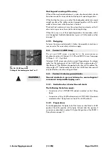
Setting up a ground stack consisting of J-SUB and J8/J12 cabinets first
the subwoofer cabinets are stacked on the floor and connected
together with their Front and Rear links - Fig. 41. The J Flying frame is
placed on top of them to support the J8/J12 cabinets
Set up
1. Remove the transport lid of the J-SUB cabinet.
2. With one person at each side of the J-SUB tip the cabinet on its
bottom panel.
3. For additional J-SUB cabinets proceed in the manner as described in
step 1 and 2 and position the cabinets on top of each other.
4. Interconnect the cabinets with the Front and Rear links of the
cabinets - Fig. 41.
Attaching the Flying frame
5. Position the Flying frame on top of the uppermost J-SUB cabinet with
the hole grid of the center bar facing upwards.
6. Fix the Flying frame to the top J-SUB cabinet with the Front links of
the cabinet and the Splay link of the frame (J-SUB position).
Attaching the J8/J12 cabinets
7. The assembly of the J8/J12 cabinets on top of the J-SUB cabinets is
carried out in the same manner as described in section 4.4.3 J8/J12
ground stack assembly on page 27.
Wiring
8. Connect the cables and link cables according to the number of
amplifier channels and cabinets used.
Securing the set up
9. Secure the ground stack against movement and possible tipping
over.
Derigging
To dismantle the ground stack, follow the assembly instructions in
reverse order. The same safety instructions apply.
4.5.1. J-SUB stacks
Conventional J-SUB stacks are set up in the same manner as described
in the previous section. For conventional ground stacks of J-SUB
cabinets we also recommend to interconnect the cabinets with their
Front and Rear links - Fig. 43.
Secure the stack against movement and possible tipping over.
J-Series Rigging manual
(1.3 EN)
Page 29 of 34
a)
b)
Fig. 41: Interconnection of the J-SUBs
a)
b)
Fig. 42:J-SUB and J8/J12 Ground stack
Assembly of the Flying frame
a)
b)
Fig. 43: Interconnection of the J-SUBs
Summary of Contents for J Series
Page 1: ...J Series Rigging manual 1 3 EN...
Page 33: ......


