background image

6

5

4

2

1

P ar t N o .

D ia g ra m

Qt y

P a rt No .

Di a gr a m

3

7

8

9A-1

9A -2

4

4

2

4

10

11A

12

9C

6

11A -1

11B

2

12A

12B

2

13

12

R o o f/ F ro n t/ B ac k c o v er

1 4.15 .16

1 7

R op e f o r f i xi n g c ov e r

18

19

20

M1 4X 3 0
M1 4X 7 0
M1 2X 5 0

M14X 5 0

21

1

1

Q ty

W 6 X L 1 2 X S 3 . 5 X H 5 . 5 M ( w i t h 3 . 5 X 3 . 5 m a c h i n i n g d o o r )

10

10

10

102

6

3 8

228
48
4
24

10

2

2

9A-3

9 B

1

1

9A-4

4

1

12-12-2016

Summary of Contents for Titanium Tent

Page 1: ...12 12 2016 6x12x3 5x5 5m Manual for Titanium Tent ...

Page 2: ... a risk of rain puddles building up on top of the roof of the marquee tent Heavy rain puddles can cause the roof to collapse It is your responsibility to ensure rain puddles do not build up As a precaution make sure the roof of the marquee tent is stretched out properly and adequately over the side frames of the marquee tent and remove rain water regularly Do not unpack or repack your marquee tent...

Page 3: ... the cross tubes in front and back wall including the tensioning tube for covers at the bottom roof cover onto the bottom tensioning tubes at the both side of frame as per Figure 5 6 Then please put the rope in the sleeves at the two ends of roof cover into rings on the base the bottom of the covers to the bottom tensioning tubes 8 Please connect and tighten ropes between roof cover and front back...

Page 4: ...tration For user friendly assembly we have identified each individual component with our partcode number as indicated in the part list Please refer to the part code number and drawings to ensure problem free assembly ...

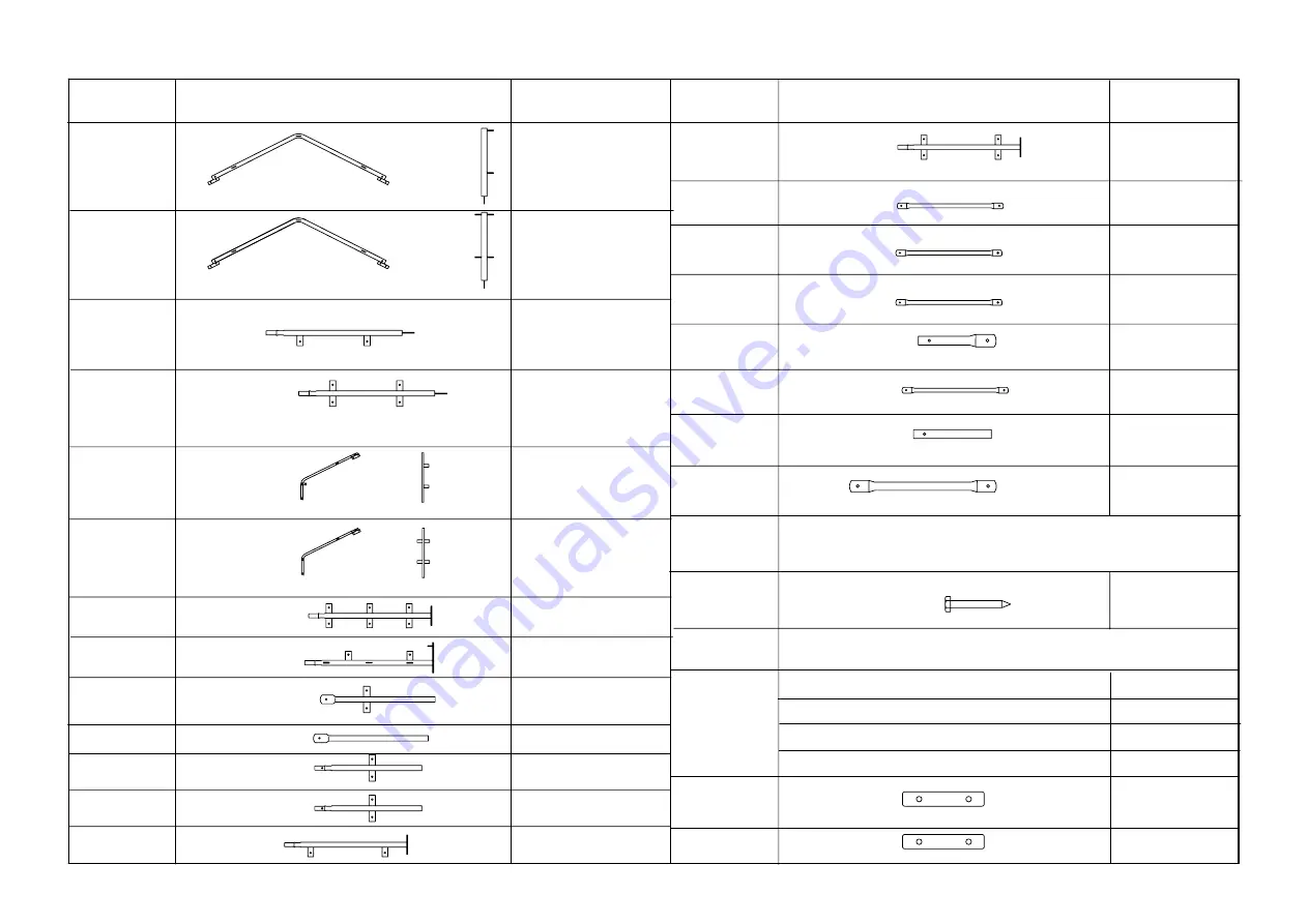
Page 5: ...panel middle leg tube size 1900mm 1 9B Lower Standing Legs with base flange in front and back panel tube size 2100mm 4 9C Lower Standing Legs with base flange in back panel middle leg tube size 2100mm 1 10 Roof purlin and horizon wall at both sides tube size 1912mm 102 11A Cross tube at two ends in front and back panel tube size 1138mm 12 11A 1 Cross tube middle in back panel tube size 1662mm 6 11...

Page 6: ...4 2 4 10 11A 12 9C 6 11A 1 11B 2 12A 12B 2 13 12 Roof Front Back cover 14 15 16 17 Rope for fixing cover 18 19 20 M14X30 M14X70 M12X50 M14X50 21 1 1 Qty W6XL12XS3 5XH5 5M with3 5X3 5machining door 10 10 10 102 6 38 228 48 4 24 10 2 2 9A 3 9B 1 1 9A 4 4 1 12 12 2016 ...

Page 7: ...2M 6M 12M 6x12x3 5x5 5M Schematic drawing of placement for base flange ...

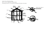
Page 8: ...10 19 13 3 5 9B 11A 11B 1 4 12A 2 10 9A 2 11A 1 9A 3 9C 9C 7 6 13 8 6x12x3 5x5 5M Frame Sketch M14x50 bolt with nut ...

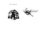
Page 9: ...19 19 19 1 2 3 4 5 6 7 8 11B 20 6x12x3 5x5 5M slant supporting tube M12x50 bolt with nut M12x50 bolt with nut M14x70 bolt with nut Frame installation procedure And connection hint ...

Page 10: ...11A 10 19 19 Frame connection hint M14x30 bolt with nut ...

Page 11: ...14 14 7 8 18 6x12x3 5x5 5M Illustration for installation and tensioning both sides of roof cover ...

Page 12: ... and rear folds Pls put the ropes in the roof cover pocket throughthe rings and pull hard the ropes At the same time pls tidy rumple on the folds Gradually when the cover is well on the frame pls knot the ropes on the rings as below show ...

Page 13: ...18 11B 12A 1 2 3 4 5 6 7 8 12B Illustration for installation of front cover As below shows edges of front cover are secured to the frame by ropes ...

Page 14: ... 8 9A 1 9C 9C 9A 2 9A 3 11A 11A 1 8 M14x30 bolt with nut As below shows the both sides and top Part of rear cover are tightened to the frame by rope The bottom part of rear cover is fastened to the tensioning tube by rope as below shows ...

Page 15: ...17 7 8 9B 9C 6x12x3 5x5 5M stake peg ...

Page 16: ......

Reviews: