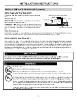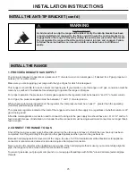
WARNING
When using test pressures greater than 1/2 psig to pressure test the gas supply system of the residence, disconnect the
range and individual shut-off valve from the gas supply piping. When using test pressures of 1/2 psig or less to test the
gas supply system, simply isolate the rane from the gas supply system by closing the individual shut-off valve.
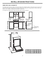
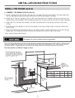
Recommended Gas and Electric Supply Location
%
0LQLPXP
GLVWDQFHWR
ZDOOVDERYHWKH
FRRNWRSRQHDFK
VLGH
&
'
$
(OHFWULFDO
&RQQHFWLRQ
$UHD
*DV
+RRNXS
$UHD
&KHFNORFDOFRGHV
EHIRUHPDNLQJ
FRQQHFWLRQV
0LQ
0LQ
$
0RGHOV
$
%
&
'
:LGH
ø
µ
ø
µ
:LGH
ø
µ
ø
µ
127(
5HFRPPHQGHGJDVKRRN
XSORFDWLRQVEHKLQGUDQJH*DV
ILWWLQJVDQGVKXWRIIYDOYHVKRXOG
127SURWUXGHPRUHWKDQIURP
WKHZDOOWRDOORZWKHUDQJHWRILW
DJDLQVWWKHZDOO
0D[
3”
NOTE: Recommended gas hook-up
locations behind range. Gas
fi
ttings
and shut-off valve should NOT protrude
more than 2” from the wall to allow the
range to
fi
t against the wall.
Check local codes
before making con-
nections
Electrical
Connection
Area
Gas Hookup
Area
Minimum
distance to
walls above the
cooktop on each
side.
26
INSTALLATION INSTRUCTIONS
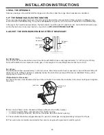
Fire hazard: do not use a
fl
ame to check for gas leaks.
INSTALL THE RANGE (cont`d)
2. CONNECT THE RANGE TO GAS (cont`d)
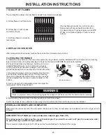
A. Install a manual gas line shut-off valve in the gas line in an easily accessed location outside of the range. Make sure
everyone operating the range knows where and how to shut off the gas supply to the range.
B. Install male 1/2”
fl
are union adapter to the 1/2” NPT internal thread at inlet of regulator. Use a backup wrench on the
regulator
fi
tting to avoid damage. When installing the range from the front, remove the 90° elbow for easier installation.
C. Install male 1/2” or 3/4”
fl
are union adapter to the NPT internal thread of the manual shut-off valve to keep it from
turning.
D. Connect
fl
exible metal appliance connector to the adapter on the range. Position range to permit connection at the
shut-off valve.
E. When all connections have been made, make sure all range controls are in the off position and turn on the main gas
supply valve. Use a liquid leak detector at all joints and connections to check for leaks in the system.
*Te
fl
on: registered trademark of Dupont
Models
A
B
C
D
20” Wide
20
⅜
”
2”
2”
2 ½”
24” Wide
24
⅜
”
2”
3”
5 ½”

