background image

28 

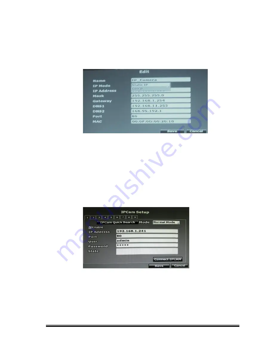
The  IP  Cam  has  to  be  under  the  same  LAN  with  NVR  in  order  to  be 

successfully connected. 

Ex.

 If the NVR IP address is 192.168.10.33, the IP 

Cam  IP  address  should  be  192.168.10.X.  You  can  edit  the  IP  Cam  IP 

address here or on the IP Cam. 


B-2. Normal Mode 


1. Enable: Choose “Normal Mode” 


2. IP Address

Insert the IP address of the connecting device. 


3. Port

Insert the port number of the connecting device. Default port: 80 


Summary of Contents for H.264 DVR

Page 1: ...USER MANUAL 9 CHANNELS HYBRID DIGITAL VIDEO RECORDER ...

Page 2: ...PURSUANT TO PART 15 OF THE FCC RULES THESE LIMITS ARE DESIGNED TO PROVIDE REASONABLE PROTECTION AGAINST HARMFUL INTERFERENCE WHEN THE EQUIPMENT IS OPERATED IN A COMMERCIAL ENVIRONMENT THIS EQUIPMENT GENERATES USES AND CAN RADIATE RADIO FREQUENCY ENERGY AND IF NOT INSTALLED AND USED IN ACCORDANCE WITH THE INSTRUCTION MANUAL MAY CAUSE HARMFUL INTERFERENCE TO RADIO COMMUNICATIONS OPERATION OF THIS EQ...

Page 3: ...ce of insinuated dangerous voltage within the products enclosure that may be of sufficient magnitude to constitute a risk of electric shock to persons The exclamation point within an equilateral rhombus is intended to alert the user to the presence of important operating and maintenance servicing instruction in the literature accompanying the product CAUTION TO REDUCE THE RISK OF ELECTRIC SHOCK DO...

Page 4: ... LOCAL LAWS AND STATUTES COIPCERNING THE MONITORING AND RECORDING OF VIDEO AND AUDIO SIGNALS ULTRAK SHALL NOT BE HELD RESPONSIBLE FOR THE USE OF THIS SYSTEM IN VIOLATION OF CURRENT LAWS AND STATUTES COPYRIGHT THE TRADEMARKS MENTIONED IN THE MANUAL ARE LEGALLY REGISTERED TO THEIR RESPECTIVE COMPANIES ...

Page 5: ...P 43 3 6 NETWORK SETUP 48 3 7 AUTHORITY SETUP 58 3 8 DISK MANAGEMENT 61 3 9 SYSTEM SETUP 64 3 10 EX DEBUG MESSAGE 68 4 NVR PLAYBACK 71 4 1 TIME SEARCH 73 4 2 EVENT SEARCH 74 4 3 BACKUP 75 4 4 SYSTEM LOG 76 5 BACKUP PLAYBACK 77 5 1 MAIN SCREEN SETTING 77 5 2 PLAYBACK OPERATION 82 6 NETWORK VIEWING PLAYBACK 85 6 1 IP ADDRESS SETUP ON PC SITE 85 6 2 OPTIONAL MICROSOFT INTERNET EXPLORER SETUP 87 6 3 L...

Page 6: ...port 4T HDDs x1 Support Privacy Mask Support HDMI Video interface Support CMS Central Management System control Graphic User Interface GUI Support time point backup function under Ethernet remote control mode The user can select any time period to process backup from remote side Support time search event search function under Ethernet remote control mode Up to four online clients for independent r...

Page 7: ...NTSC per CH IP Camera Bit rate Single CH up to 8Mbps Total up to 24Mbps Analog Video Input Max 8 channels Analog Resolution 960H 960 x 480 NTSC 960 576 PAL D1 720 x 480 NTSC 720 576 PAL Analog Live time Display Rate 8 x 30 Frame sec NTSC 8 x 25 Frame sec PAL Analog Audio Input 4 channels Hybrid DVR Functions Camera Name Max 20 characters Screen Split Control 1 4 9 Image Control Contrast Brightness...

Page 8: ...x 576 PAL Half D1 720 x 240 NTSC 720 x 288 PAL CIF 360 x 240 NTSC 360 x 288 PAL Recording Rate Per Channel 960H Up to 30 FPS NTSC Up to 25 FPS PAL D1 Up to 30 FPS NTSC Up to 25 FPS PAL Half D1 Up to 30 FPS NTSC Up to 25 FPS PAL CIF Up to 30 FPS NTSC Up to 25 FPS PAL Backup Type USB Remote Client Software Monitoring Environment Hunt CMS APP Web site IP Analog cam Live View 9 Channels Remote Search ...

Page 9: ...r USB x2 Networking Type Static DHCP PPPoE DDNS Environment Operating Temperature 0 45 32 113 F Humidity 0 80 RH non condensing Language Type English Traditional Chinese Simple Chinese Russian Italian Japanese Czech France Germany Spanish Portuguese Physical Color Black Dimensions W x H x D 218mm 44mm 202mm SPECIFICATIONS ARE SUBJECT TO CHANGE WITHOUT NOTICE ...

Page 10: ...L NAME OPERATION 1 LED POWER REC PLAY HDD LED indicators 2 CHANNEL Video Control Channel Split buttons 3 MENU Menu functions 4 ENTER COPY Enter Copy button 5 4 3 2 1 5 7 6 8 19 9 21 20 10 11 12 16 17 18 15 14 13 22 USB Connector USB Mouse Connector ...

Page 11: ... OUT Audio Output 2 VIDEO OUT VGA LCD monitor connector 3 ETHERNET RJ 45 connector 4 AUDIO IN Audio input 5 POWER Power adapter AC 12V 5A connector 6 VIDEO IN BNC video input 7 DI DO 2 alarm in RS485 1 relay out 8 VIDEO OUT HDMI HDMI video output ...

Page 12: ... channel screen or split screen b The external relay built in buzzer can be triggered c The alarm time point can be recorded in the event list and you can search for the event in playback d On the channel which the alarm is triggered the icon pops up to remind the user e The pre post alarm recording video can be sent to e mail uploaded to FTP f The CGI can be sent to an http server B When the Exte...

Page 13: ...d to FTP e The CGI can be sent to an http server C When Video Loss Alarm occurs a The external relay built in buzzer can be triggered b Alarm time point can be recorded in the event list and you can search for the event in playback c On the channel which the alarm is triggered the icon pops up to remind the user d The CGI can be sent to an http server ...

Page 14: ...14 2 4 ALARM IN CONNECTION D RS 485 sends receives D RS 485 sends receives GND Ground ALARM IN 1 8 Alarm input N C Relay Normally close N O Relay Normally open COM Relay Common ...

Page 15: ...15 EX1 Connect GND Alarm to external IR detector EX2 Connect N O COM to external siren Depending on the external device type you may connect N C COM to the external device ...

Page 16: ...amera joystick controller To control the PTZ camera via DVR please check the CAMERA ID BANDRATE default at 9600 bps and the RS 485 cable Under Two Core connection the controller can control the speed dome without any built in protocol into the NVR Moreover one keyboard can be connected to a of MAX 256 units ...

Page 17: ...17 3 SYSTEM SETUP 3 1 SETUP MENU INTERFACE GUI A CAMERA SETUP B RECORD SETUP ...

Page 18: ...18 C ALARM SETUP D NETWORK SETUP E AUTHORITY SETUP F DISK MANAGEMENT ...

Page 19: ...19 G SYSTEM SETUP H EXIT 3 2 LIVE VIEWING AND POP UP MENU ...

Page 20: ...g an IP address to the IP Cameras for getting automatic connection The system will check addresses from 192 168 X 0 with X being the NVR LAN Once the user executes the function the IP address of the IP Camera will changed if the IP Camera and the NVR address is under a different LAN The IP address will be assigned from 192 168 X 50 B GUI MENU BAR ...

Page 21: ...n split screen the switch dwell interval is 5 sec D DISPLAY CONTROL On live view or playback mode use display control to switch the camera channels E PTZ CONTROLLER On live view mode click this button to open the PTZ control panel NOTE Only for PTZ cameras After pressing the minimization icon the control panel becomes smaller ...

Page 22: ... using the direction key on the control panel If a fisheye camera is connected PTZ Steps 1 Select the channel number you want to setup 2 Select the View Mode 360 degrees or 180 degrees 3 Select the camera location ceiling desk or wall 4 Select the split screen pattern 360 degree panorama view sub screens x4 180 degree flat view sub screens x2 sub screens x4 ...

Page 23: ...ol Mode Select the E PTZ moving mode step by step or continuous 8 The AutoPan Stop and Patrol buttons are invalid here if the fisheye camera doesn t support those function F DISK INFORMATION Displays the disk information on live mode G DIGITAL ZOOM On live full screen mode left click to select a zoom in or zoom out range for the image The users can right click for disabling this function NOTE the ...

Page 24: ...nt panel controller K SOUND INPUT SOUND OUTPUT PTZ CONTROL There little icons displayed on the top right of the live vide of every channel Click to enable sound output Click the button to show the control board Please note that if those functions are not supported by the camera linked you will not see the corresponding icons The sound options do not affect the audio recorded into the video As long...

Page 25: ...ual Recording M FAST SWAP On Split Screen mode right click on one specific screen view for displaying a list all 9 channels By clicking on the desire channel the views between the channels will be swapped N FAST SWITCH On one single view mode right click on the live view for displaying a list all 9 channels By clicking on the desire channel the view will be switch by the selected channel ...

Page 26: ...26 3 3 CAMERA SETUP A Analog Camera CH 1 6 analog CH 7 8 optional ...

Page 27: ...Search button and click the Search Device button The NVR will search the IP CAM devices which IP address are setup as the same domain as the NVR IP address Moreover by clicking on the IP Cam on the list will import the device information to the channel automatically without any manual key in step ...

Page 28: ... IP address is 192 168 10 33 the IP Cam IP address should be 192 168 10 X You can edit the IP Cam IP address here or on the IP Cam B 2 Normal Mode 1 Enable Choose Normal Mode 2 IP Address Insert the IP address of the connecting device 3 Port Insert the port number of the connecting device Default port 80 ...

Page 29: ...TP Mode Under RTSP Mode the NVR only support IP address indication live video and video recording Other functions like motion detection are not supported Key in the IP address port username and password of the device you are connecting to the NVR You can find the information on the IP Camera To link to the IP camera check the RTSP Path settings of your IP camera and key in the corresponding values...

Page 30: ...mera Examples of some RTSP settings RTSP Path 1 IP Cam Main stream RTSP Path 2 IP Cam Sub stream Result 1920 x 1080 640 x 480 OK NVR takes 1920x1080 streaming for single channel view mode and 640x480 streaming for split screen mode 1920 x 1080 N A Fill in nothing on RTSP Path 2 Error Message Invalid Substream Resolution Please modify IP Cam NVR takes 1920x1080 streaming for ...

Page 31: ...d 640x480 streaming for split screen 1920 x 1080 1920 x 1080 Error Message Invalid Substream Resolution Please modify IP Cam NVR takes 1920x1080 streaming for both single channel view and split screen However it can only allow 640x480 resolution for split screen so it shows error in return B 3 ROI This function allows users to set up the channel as an attached channel An attached channel is based ...

Page 32: ...ect a connected normal RTSP channel in the drop down menu 3 Ratio Use the arrows to adjust the zoom ratio and press the red frame to drag it to the area that you want it to show on the live view screen C IP Cam Video Setup Setup for Analog Camera ...

Page 33: ... 1 Megapixel the resolution options support 1M 2M 4M 6M 8M For H 264 IP Cameras less than 1 Megapixel the resolution options include Best High Standard Medium Low For MPEG IP Cam the resolution options support Standard Medium Low The highest resolution option is standard due to the chip performance limits of IP Cam C 3 FrameRate Click drop down list to change the frame rate of connecting device ...

Page 34: ...Cam Image Setup Setup for Analog Camera Setup for IP Camera D 1 Display Use the mouse to enable or disable the camera display on the screen D 2 Title Use the mouse to setup the title of the connecting IP device ...

Page 35: ...e hue level The adjustment value is between 0 255 D 7 Saturation Press or to change saturation level The adjustment value is between 0 255 D 8 Sharpness Press or mouse wheel to change sharpness level The adjustment value is between 0 15 D 9 Period You can adjust two different image settings and apply them at different periods of time D 10 Day Night There are 3 different modes for your camera to pe...

Page 36: ...ay be assigned in Time mode Set the time length to determine how long your Period may be assigned The other Time will be automatically assigned to the other Period left D 13 Default You may choose this option to reboot all the system settings to its very beginning E Motion Setup E 1 Relay Dwell Press or to change the relay time or disable the relay function E 2 Buzzer Dwell Press or to change the ...

Page 37: ... green area for motion detection E 5 Area3 Sensitivity Press or to change the sensitivity of setup motion area in Area3 Click Motion Area Setup and drag a red area for motion detection After dragging an area right click and select Exit with saving to complete the area setup Select Enable All to set up global motion detection Select Clean All to clean the area of the current color in the view Selec...

Page 38: ... and playback recording F 1 Area1 Tick the Area1 box and click Area Setup to drag a blue area for masking F 2 Area2 Tick the Area1 box and click Area Setup to drag a green area for masking F 3 Area3 Tick the Area1 box and click Area Setup to drag a red area for masking ...

Page 39: ...clean the area of the current color in the view Select Exit Without Saving to go back to mask setup menu and the setting you just changed will not be saved G IP Cam Audio Setup If the channel is ticked the sound from camera will be recorded into the playback video On the contrary no sound will be recorded in the playback video of the channel which is not ticked ...

Page 40: ...ggered If you set 5 sec for pre alarm and 5 sec for post alarm the alarm recording length will be total 10 sec B Record Mode The record mode will be applied to all channels simultaneously When recording the NVR record both main streaming and sub streaming from IP Cam Use the drop down list to switch the recording mode 1 Manual Click to start recording Click to stop recording 2 Schedule a Schedule ...

Page 41: ... the schedule The tag Alarm Recording includes all the alarm types b Mail Schedule Setup Select the time that the recording video is sent to the mail address No mail will be sent during the NO MAIL time period even if the motion detection is triggered The tag ALARM MAIL refers to both external alarm and DI from camera c FTP Schedule Setup ...

Page 42: ...ction is triggered The tag ALARM FTP refers to both external alarm and DI from camera 3 Alarm Trigger Start recording when any type of alarm event occur The recording video length is according to the setting of Pre Alarm Record Time or Post Alarm Record Time C Mobile Streaming Setup Choose ON to record the streaming for mobile viewing ...

Page 43: ...M SETUP A Alarm Trigger Setup A 1 Alarm Auto Switch Use the drop down list to switch the alarm auto switch When the alarm is triggered the screen will switch to full screen split screen 9CH split screen or disable ...

Page 44: ...en the DI signal is received from the camera the alarm will be triggered A 4 Ext Alarm Detection Use the drop down list to switch the external alarm detection When the external alarm is detected the alarm will be triggered A 5 Ext Alarm Mode Use the drop down list to switch the external alarm mode If the external alarm is setup for normal open the option has to switch to N O for the contrary the o...

Page 45: ...ay Time option the user can press or to switch the external buzzer time and video loss buzzer time The adjustment value is from off to 99 seconds as well The Value of Ext Alarm Buzzer Relay Time determine the buzzer relay time of both external alarm in and digital input IP Cam C Alarm Event Setup There are eight types of events that can be selected When the selected items occur and triggered the l...

Page 46: ...gle Channel Screen Split Screen Condition Alarm Setup Alarm Trigger Setup Alarm Auto Switch set to Full Screen Split Screen X X X Trigger Relay Buzzer Condition Camera Setup Motion Setup Relay Buzzer Dwell not set to Off It s enabled as long as the necessary condition is meet p Trigger length setting Alarm Setup Alarm Output Setup Relay Buzzer Time p Ext Alarm Relay Buzzer Time length setting dete...

Page 47: ...when both necessary nondition and one of above three conditions are met p Mail FTP server setting Network Setup Mail FTP Setup Fill in server information p Pre Post alarm recording length setting Record Setup Pre Post Alarm Record Time X Http CGI Network Setup HTTP Notification Setup Fill in Http server information and tick Enable p 1 Another interpretation Send E mail Upload to FTP with Pre Post ...

Page 48: ...48 3 6 NETWORK SETUP A IP ADDRESS SETUP A 1 IP Mode Press drop down list to change IP mode to Static IP or DHCP A 2 IP Address Set the NVR IP Address ...

Page 49: ...sually set to 255 255 255 0 A 4 Gateway Set NVR gateway A 5 DNS1 DNS2 Key in DNS1 and DNS2 that provided by ISP A 6 Default Gateway Set the Default Gateway A 7 WebPage Port Set the NVR http port for web browser The default port is 80 B PPPoE SETUP ...

Page 50: ...ocal ISP B 3 Password Insert the password which provided from local ISP B 4 Password Confirm Insert the password again to confirm the password B 5 State Present the current status of PPPoE function B 6 Send Mail After Dialed Click the drop down list to enable or disable the function B 7 Subject Insert the mail subject when dialed successfully ...

Page 51: ...ction C 2 Provider Click the drop down list to select the DDNS provider C 3 Host Name Type in the registered host name in the selected provider C 4 User Name Type in the registered user name in the selected provider C 5 Password Type in the registered password in the selected provider ...

Page 52: ...fully now log by http username ddns camddns com Registered successfully Updating Failed the name is already registered Updating Failed please check your internet connection D MAIL SETUP D 1 Enable Tick Alarm to send video to the mail address when external alarm or DI from IP Cam is triggered Tick Motion to send video to the mail address when motion detection is triggered ...

Page 53: ...The user name while log in to the mail server D 5 Password The password while log in to the mail server D 6 Sender s Mail The sender s account when send the mail via this mail server D 7 Receiver s Mail The receiver s mail address D 8 BCC Mail The receiver s mail address for Bcc Mail D 9 Subject The subject while sending the mail D 10 Secure Connection ...

Page 54: ...mail for Alarm in and or Motion detection E 2 Power On Will send a notification via email when the NVR starts or reboots E 3 Start Record Will send a notification via email when the NVR starts recording E 4 Record Error Will send a notification via email when the recording failed usually represents hardware failed in the HDD ...

Page 55: ...E 6 Load Default Will send a notification via email when the NVR load the default settings F FTP SETUP F 1 Enable Tick Alarm to upload video to FTP when external alarm or DI from IP Cam is triggered Tick Motion to upload video to FTP when motion detection is triggered F 2 FTP Server The IP address of FTP Server ...

Page 56: ...log in to the ftp server E 4 Password The password while log in to the ftp server E 5 FTP Port The port number of file transmission Default value is 21 E 6 Path The ftp path where the user wants to save the information G DHCP Server Setup ...

Page 57: ...ess which is according to the setup IP address range start and end IP Address to the connecting IP CAM setup DHCP function as well G 2 Start IP Address Use the virtual keypad to insert the start IP Address of DHCP server G 3 End IP Address Use the virtual keypad to insert the end IP Address of DHCP server G 4 Lease Time Press or to change the lease time of DHCP server H UPNP Port Forwarding Setup ...

Page 58: ...checkbox to enable or disable UPNP port setup H 2 External HTTP Port Use the virtual keypad to insert the external http port H 3 External RTSP Port Use the virtual keypad to insert the external RTSP port 3 7 AUTHORITY SETUP ...

Page 59: ...e user does not have to insert the username password and will view the live image via IE browser C Password Protection Use the checkbox to enable or disable the authority of password protection D Keyboard Lock Use the checkbox to enable or disable the operation of the control bar which is in the right hand side of live view The control bar cannot work when the keyboard lock is activated E Auto Log...

Page 60: ...F User Management The administrator can setup the user management permission and the user authority management F 1 Permission Use the mouse for clicking the checkbox to modify and alter the user authority ...

Page 61: ...61 F 2 Add User After clicking the button the setup page will be called out as the following The administrator can distribute the authority and the permission for the new user 3 8 DISK MANAGEMENT ...

Page 62: ...ing ratio the buzzer will start buzzing C Auto Deletion If select ON the users cannot find the recording data that is older than the reserve day For example On 2012 10 19 17 40 The auto deletion is set as ON The reserve day are set as 3 If the recording data is older than 2012 10 16 17 40 will not be indicated on the playback menu D Reserve Day Use or to setup the saving days day between 1 30 days...

Page 63: ...63 E Storage Information The information of storage device will present in this page F Format HDD Insert the user name and password while performing the HDD format function ...

Page 64: ...VR ID The adjustment value is between 0 32 C Language Use the drop down list to change the NVR language Currently there are English Traditional Chinese and Simplified Chinese as the available three options D Date Format Use the drop down list to change DATE There are three modes DD MM YYYY YYYY MM DD and MM DD YYYY ...

Page 65: ... column F Software Update Click button to perform firmware updating G Configure Setup Click the checkbox to select which item can be setup by the user The user can also load the setting to factory default load the configuration from USB and backup configure to USB ...

Page 66: ...reover if the user clicks the enable checkbox and the button within the NTP Setup block the time of the NVR will be synchronized with the NTP Server I Day Light Saving Time After enabling the daylight saving time function the user can use the drop down list to select the start time and the end time of daylight saving time After complete ...

Page 67: ...mation Display and Camera Title Display K Monitor Adjust The user can use or to adjust the monitor settings Brightness Contrast Hue and Saturation The Resolution can be adjusted Please check the frame rate that your LCD monitor support before any adjustment If you select a resolution not compatible with the LCD monitor the system will automatically undo the recent changes ...

Page 68: ...Start and Detect IPcam 3 10 EX DEBUG MESSAGE The purpose of the following procedure is to export a HDD debug message file If the user has problems with the NVR the technician can analyze the file and find the cause of problem Plug in a USB disk Enter the Authority Setup page and make sure the option HDD Format Require Password Confirmation is ticked Enter the Disk Setup page Click Format HDD ...

Page 69: ...name column to login No password is required The screen turns to the Advance Setup page Click download It takes about 10 seconds to export the file When the downloading is complete a message pops up to remind the user Click OK ...

Page 70: ...70 Now the debug message file should have been in your USB disk Please turn the file dbgms tar to the technician ...

Page 71: ...e press this button to backup recording ha0 video to the USB disk Press this button again to finish the backup To perform a single image backup jpg single image backup press first and then click the Record Backup button to back up the necessary image B AUDIO VOLUME Press this button for the audio volume control board to pop up ...

Page 72: ...control to switch the camera channels D DIGITAL ZOOM On live full screen mode left click to select a zoom in or zoom out range for the image The users can right click for disabling this function NOTE the image can be zoom in to max 16x E RECORD AND PLAYBACK CONTROL ...

Page 73: ...4 1 TIME SEARCH Select the start of the playback time and then click the button to playback the recorded data If a period of time contains the recorded data the time point within this page will become red ...

Page 74: ...to the event search page the user can click the event log item which is shown on the list for starting playback Moreover the user could click the button to select the specific event option to filter the event option shown on the list ...

Page 75: ...use the drop down list to select the storage device the backup time selection mode and time Please click the button to start backup TIME MODE Click or to select the start and end backup time Moreover click the button to select the channel which is going to backup ...

Page 76: ...mum quantity of records is 2000 Click the button to perform further data filter actions After completing the specific item selection click the button to save the settings When returning to the system log page it will only reveal the specific selected items After click button ...

Page 77: ... MEMORY 512MB or above VGA 64MB or above VGA RESOLUTION 1024 x 768 OS Windows XP 2000 or above NETWORK BANDWIDTH Upload Speed is 256kbps or above 5 1 MAIN SCREEN SETTING The player D6Viewer exe is used to play the NVR backup video D6Viewer exe can be obtained via the Internet moreover while performing USB backup and DVD RW backup the software will be built automatically as well ...

Page 78: ...ndows system may not read it Please use the software Ext2Fsd to assign a drive letter to the HDD Ext2Fsd is in the attached CD or can be downloaded from the Internet Start the Ext2Fsd and it will detects all the disks connected with your PC Right click on the NVR HDD and choose Change Drive Letter Select video source Playback Control Save as AVI Time Event Search Split Screen Channel Selected ...

Page 79: ...79 Click Add Assign a letter to the HDD then click OK so that the HDD get a drive letter and can be recognized by Windows ...

Page 80: ...80 2 Under HDD play mode select the NVR HDD to load the video file in the HDD C File Play 1 You can use D6Viewer to open a single video backup file Under file play mode select Open ...

Page 81: ...81 2 Choose the path the haX file reserved and pick the file to playback 3 Press the play icon to play the video or pause picture ...

Page 82: ...OPERATION A TIME SEARCH Select the Date and Time and then click to play the video B EVENT SEARCH After pressing the button it will display all the events which are saved within the NVR HDD Shown in the following image ...

Page 83: ...83 C LOG Click to check the log records D ZOOM Tick the Zoom box and drag an area on the screen Click the area to zoom in ...

Page 84: ... TO AVI 1 Select the specific channel to backup 2 During video playback mode press the button to start 3 Make up a filename and path than press the button to start the AVI backup 4 Press the button to finish the backup ...

Page 85: ...bove VGA 64MB or above VGA RESOLUTION 1024 x 768 OS Windows XP 2000 NETWORK BANDWIDTH Upload Speed is 256kbps or above 6 1 IP ADDRESS SETUP ON PC SITE When installing cameras inside the LAN or using a network cable to connect them to PC IPInstallerEng exe will set up the IP address of those cameras On Windows XP SP2 or above the following Windows Security Alert will popup Please click on Unblock ...

Page 86: ...rect network parameters without blank spaces On Device Lists the software lists all servers By clicking on the server the IP settings will be show on the right side After editing the parameters and clicking on Submit the following dialogue box will popup Then it will reboot the device with the new parameters ...

Page 87: ... IE Tools Internet Options Security Custom Level Security Settings Download unsigned ActiveX controls Enable or Prompt recommend B IE Tools Internet Options Security Custom Level Security Settings Initialize and script ActiveX controls not marked as safe Enable or Prompt recommend 1 2 ...

Page 88: ...88 3 4 5 All the three options above are all based on the prompted interfaces Please click YES OPTION 2 ADD TO TRUSTED SITES IE Tools Internet Options Security Trusted sites Sites ...

Page 89: ...ACTIVEX C ACCOUNT PASSWORD LOGIN After the IP setup and connecting to the network or LAN type directly the IP address on the IE Browser directly The following User name Password Login window will popup Default user name admin Default password admin ...

Page 90: ...90 6 4 REMOTE CONTROL LIVE VIEWING A NVR Configuration Get into the NVR network menu PTZ Control System Time Screen Format Playback REC Time Point Backup NVR Configuration ...

Page 91: ...91 B PTZ Control PTZ control function panel C SYSTEM TIME Live viewing mode The current live viewing time Direction Keys PTZ Zoom in out Preset Point Setup Auto Pan Function Up to 32 preset points ...

Page 92: ...th full screen E Full Screen Click again to return F REC Click to start record the live video to the PC or storage device The saved file is ha0 file G Playback Click and select time playback or event playback H Time Point Backup Click to select backup time point The saved file is ha0 file ...

Page 93: ... Click the button for the playback window to popup A HDD Select The user can select HDD1 or HDD2 for playback B Playback Time The user can select the time by pressing Time Search for playback HDD Select Event Search Playback Time Time Search ...

Page 94: ...n select the event item by pressing Event Search for playback TIME POINT BACKUP Click to operate the Time Point backup First select the Start and End backup time Then click the Save button to select the path on the PC where the user is going to backup the data After that press the OK button to start the backup ...

Page 95: ...80526113258 ha0 will be 2008 05 26 11 32 58 OTHER FUNCTIONS Right click on any channel The following menu will pop up A Snapshot Save a single picture from the image B Play audio Play audio off the channel Note a remote user can receive audio from the NVR The playback performance is not influenced if the sound is being recorded ...

Page 96: ...RMATION SERVER NAME This name will be shown on the IP Installer MAC ADDRESS The MAC address It cannot be changed A 2 NTP Setting TIME ZONE It can only be modified via adjust DATE and TIME SETUP in the NVR Menu NTP SERVER Change the time of the NVR via NTP Server ...

Page 97: ... highest User and Guest Administrator Posses the highest level of authority to operate full functions within network User Live Image and Video Playback authority Moreover PTZ controlled is included as well Guest Live Image authority only Default administrator account Username admin Password admin ...

Page 98: ... by ticking at the choice below Ex Ticking at PTZ allows the new user to control the PTZ functions You can apply the authority settings to the channel you choose The new user has no authority in those channels that are not selected Modify Click Edit for the following window to pop up After typing the Password and confirming it click on OK You can also change the masking channel here ...

Page 99: ...TEM UPDATE Firmware Upgrade Click on the Browse button to select the latest firmware and then press the Upgrade button to upgrade the firmware Load Default Click Browse to choose a file You can load the setup from your computer if you clicked on Download and saved the settings before ...

Page 100: ...owser 2 Run the unreg file in the CD to automatically remove the existing ActiveX component WATCH_16R from your PC 3 Log in the DVR NVR via web browser again and the browser will require you to install the new version of ActiveX control Manual Uninstall If the tool does not work please follow the following steps to uninstall the ActiveX control manually 1 Look for the files KConfig ocx and WATCH_1...

Page 101: ... WINDOWS system32 WATCH_16R KConfig ocx u 3 Start Run Key in regsvr32 The path of WATCH_16R ocx u Click OK Ex regsvr32 C WINDOWS system32 WATCH_16R WATCH_16R ocx u 4 Log in again into the DVR NVR via web browser The browser will ask you to install the new version of ActiveX control ...

Page 102: ...rotocol DHCP mode the DHCP server setting is done automatically STATIC IP Input the IP address Subnet Mask and Gateway based on the network environment D 2 UPNP PORT FORWARDING When a router is used you can enable this function to allow the user to link the device in the intranet ...

Page 103: ...DSL dial function Username Username for ADSL account Password Password for ADSL account After dialed successfully new IP address will appear E 2 SEND MAIL AFTER DIALED Click on Enabled to enable the SEND MAIL AFTER DIALED function You can also give a subject for the mail ...

Page 104: ...104 F NETWORK DDNS SETTING Click on Enabled to enable the DDNS function F 1 DYNDNS ORG ...

Page 105: ...WORD The registered password in DYNDNS ORG SCHEDULE UPDATE A period of time to update IP address STATE 1 Updating Information update 2 Idle Stop service 3 DDNS registered successfully now log by http username ddns camddns com Registered successfully 4 Updating Failed the name is already registered 5 Updating Failed please check your internet connection ...

Page 106: ...camddns com USERNAME Type in the registered username in DDNS CAMDDNS COM SCHEDULE UPDATE The period of time to update IP address STATE 1 Updating Information update 2 Idle Stop service 3 DDNS registered successfully now log by http username ddns camddns com Registered successfully ...

Page 107: ...S Setting Steps Tick ENABLE to enable the DDNS function and select ddns camddns com of the provider from the drop down list In the following type the username to apply e g NVR_GODDNS After that click on the Apply button Finally the NVR domain name http NVR_GODDNS ddns camddns com will be shown on the state block ...

Page 108: ...The user has to fill in the username password and hostname for applying the account After the user applied the account successfully the dyndns org will provide complete DDNS domain name to the user 3 If setting up the IP schedule update too frequently the IP may be blocked In general scheduling an update every day 1440 minutes is recommended G NETWORK Mail FTP Click on Motion or Alarm option to en...

Page 109: ...on detection is triggered Mail Server The IP address of the Mail Server e g mail huntelec com tw SMTP Port The port of the SMTP known as Simple Mail Transfer Protocol The default value is 25 Username The username for logging into the mail server Password The password for logging into the mail server Sender s Mail The sender s account for sending mail via this mail server ...

Page 110: ...d video to FTP when motion detection is triggered FTP Server The IP address of FTP Server Username The username for logging into the ftp server Password The password for logging into the ftp server Port The port number for file transmission Default value is 21 Path The ftp path where for saving the information Finally click on the Apply button to save the settings H NETWORK DHCP Server Setup Set a...

Page 111: ...y device that can receive CGI via HTTP protocol When an alarm events occurs the NVR sends CGI to that server HTTP Server Key in the server IP address HTTP Port Key in the server port used for http protocol User Name Key in the server username Password Key in the server password HTTP CGI Key in the CGI that you would like to send to the server when an alarm events occurs ...

Page 112: ...112 J OTHERS Player Downloaded Click Player in the left list and your browser will start up downloading D6Viewer exe to your PC K OTHERS NVR SETTING The NVR settings can be changed via the Internet ...

Page 113: ...113 K 1 CAMERA SETTING Please refer to Chapter3 3 Camera Setup K 2 RECORD SETTING ...

Page 114: ...114 K 3 ALARM SETTING K 4 DISK SETTING K 5 SYSTEM SETTING ...

Page 115: ...Y Mbps LOW 0 25M MEDIUM 0 5M STANDARD 1M HIGH 1 5M AVERAGE AVERAGE AVERAGE AVERAGE 16CH 1920 960 480 320 6TB UNIT Hours IMAGE QUALITY Mbps LOW 0 25M MEDIUM 0 5M STANDARD 1M HIGH 1 5M AVERAGE AVERAGE AVERAGE AVERAGE 16CH 2880 1440 720 480 8TB UNIT Hours IMAGE QUALITY Mbps LOW 0 25M MEDIUM 0 5M STANDARD 1M HIGH 1 5M AVERAGE AVERAGE AVERAGE AVERAGE 16CH 3840 1920 960 640 The value is for reference on...

Page 116: ...31000340SV 1TB SV35 3 ST31000322CS 1TB Pipeline HD 2 ST31000525SV 1TB SV35 5 ST31000526SV 1TB SV35 5 ST31000524AS 1TB S3 7200 12 ST1000DM003 1TB S3 Barracuda ST1000VX000 1TB S3 SV35 ST1500DL003 1 5TB S3 Barracuda LP ST31500341AS 1 5TB 7200 11 ST2000DL003 2TB S3 Barracuda LP ST3000DM001 3TB ST33000651AS 3TB S3 Barracuda XP ST3000VX000 3TB SV35 ST4000DM000 4TB WD WD1600AAJS 160GB 7200 CB WD2500AAKS ...

Page 117: ...ge WD1002FAEX 1TB S3 Caviar Black WD10EACS 1TB 7200 GP WD10EADS 1TB Caviar Green WD10EALX 1TB S3 Caviar Blue WD10EARS 1TB Caviar Green WD10EFRX 1TB WD10EURX 1TB S3 AV GP WD10EZEX 1TB Caviar Blue WD10EVDS 1TB Green Power WD10EVVS 1TB 7200 GP WD15EADS 1 5TB 7200 GP WD15EARS 1 5TB 7200 GP WD15EURS 1 5TB 7200 GP WD5000AVDS 63U7B0 1 5TB 7200 GP WD15EVDS 1 5TB 7200 GP WD20EADS 2 0TB 7200 GP WD20EVDS 63T...

Page 118: ... HDP725050GLA360 500GB 7200 HCP725050GLA380 500GB 7200 HDS721050CLA362 500GB HDT721010SLA360 1TB 7200 HDS721010CLA332 1TB 7200 HDS721010CLA362 1TB HDS721010DLE630 1TB S3 7200 HDS722020ALA330 2TB 7200 HDS723020BLA642 2TB S3 7200 TOSHIBA DS7SAE202 2TB DT01ACA050 500GB DT01ACA100 1TB DT01ACA200 2TB DT01ABA050V 500GB DT01ABA100V 1TB DT01ABA200V 2TB DT01ACA300 3TB DT01ABA300V 3TB ...

Page 119: ... incorrect Please format the pen drive to FAT32 or the Pen Drive is set up to ONLY READ mode when saving the data by using Pen Drive Please change the ONLY READ mode The data cannot be burn into the CD DVD disc Please change for another CD DVD disc and backup the file in CD DVD disc storage NO FILE There is no upgrade file within the Pen Drive or the name of upgrade file does not correspond with t...

Page 120: ...cord SCHEDULE RECORD The condition is caused by trying to stop recording when performing the schedule record Please setup the record to manual mode and then stop the recording PLEASE SELECT ONE CAMERA The message will be shown while using the ZOOM function under split screen mode Please switch the screen into full screen mode and then operate the ZOOM function V1 1_140608 ...

Reviews: