


Standalone MMC Hardware Manual
67
Danaher Motion
version 15.1
Standalone MMC Control
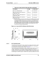
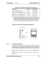
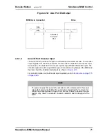
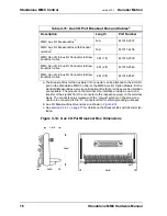
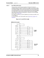
Figure 4-8: Axis I/O Port Breakout Box Dimensions
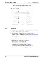
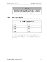
4.6.1.1
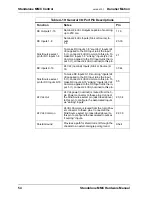
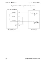
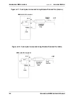
Axis I/O Port DC Outputs
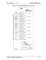
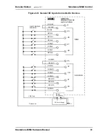
Each Axis I/O Port provides 2 sink or source 24 Vdc outputs. Each of the 2 outputs on
is a solid state switch rated at 100 ma. When the DCOSS pin is tied to the +24V, the
outputs will be in a source configuration as shown in
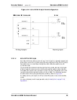
. When the DCOSS pin
is tied to COMMON, the outputs will be in a sink configuration as shown in
For safety reasons, all outputs turn off (no current flow) when a scan loss condition
occurs.
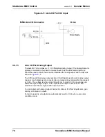
For more information on DC output operation, refer to
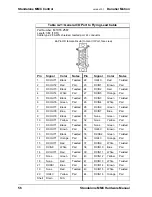
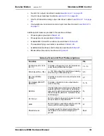
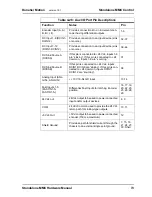
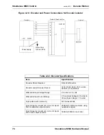
Table 4-27: Axis I/O Port Breakout Box and Cables
a
a. The Breakout Box for the Axis Connector can be attached to the A1, A2, A3, and
A4 ports on the Standalone MMC Control or the MMC Axis I/O Option Module.
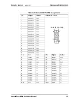
The pinouts on the terminal strip interface provide a one-to-one transfer of the
signals from the connector to the respective pin(s) on the terminal block. The
ground pin on the terminal strip provides a connection to the metal D-shell.
Description
Length
Part Number
Axis Connector Breakout Box
N/A
M.1016.2529
MMC Axis A”n” to Breakout Box Cable
.3 M (1 ft)
M.1016.2535
MMC Axis A”n” to Breakout Box Cable
.6 M (2 ft)
M.1016.2536
MMC Axis A”n” to Breakout Box Cable
.9 M (3 ft)
M.1016.2537
1.750”
2.250”
3.000”
1
9
2.250”
8
15
Summary of Contents for Standalone MMC
Page 4: ......
Page 8: ...8 Standalone MMC Hardware Manual Table of Contents version 15 1 Danaher Motion ...
Page 94: ...94 Standalone MMC Hardware Manual Standalone MMC Control version 15 1 Danaher Motion ...
Page 169: ...Standalone MMC Hardware Manual 169 Danaher Motion version 15 1 CE and EMC Guidelines ...
Page 170: ...170 Standalone MMC Hardware Manual CE and EMC Guidelines version 15 1 Danaher Motion ...
Page 171: ...Standalone MMC Hardware Manual 171 Danaher Motion version 15 1 CE and EMC Guidelines ...
Page 172: ...172 Standalone MMC Hardware Manual CE and EMC Guidelines version 15 1 Danaher Motion ...


