


Standalone MMC Hardware Manual
69
Danaher Motion
version 15.1
Standalone MMC Control
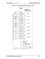
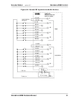
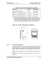
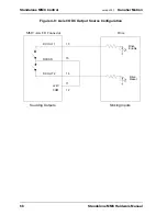
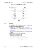
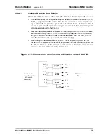
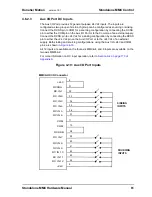
Figure 4-10: Axis I/O DC Output Sink Configuration
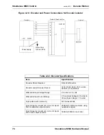
4.6.1.2
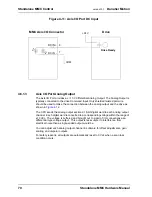
Axis I/O Port DC Input
Each Axis I/O Port provides one 24 Vdc input. Each input is an optically isolated solid
state switch. It turns on or off according to the logic state sent to it by the CPU. When
the switch turns on, current flows through the switch. When the switch turns off,
current flow stops.
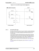
These outputs are intended to interface with the drive enable and drive reset inputs.
When an output is turned on current can flow through the switch in either direction.
This allows the outputs to be connected in a sink or source configuration. One of the
input pins should be connected to 24 Vdc or COM. The remaining input pin
should be tied to the input signal that will be switching. Refer to
.
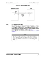
For safety reasons, all outputs turn off (no current flow) when a scan loss condition
occurs.
For more information on DC input operation, refer to
DC OUT 1
DCOSS
DC OUT 2
+24V
COM
13
15
14
11
12
Drive
Enable
Drive
Reset
Sinking Outputs
Sourcing Inputs
+24V
+24V
MMC Axis I/O Connector
Drive
Summary of Contents for Standalone MMC
Page 4: ......
Page 8: ...8 Standalone MMC Hardware Manual Table of Contents version 15 1 Danaher Motion ...
Page 94: ...94 Standalone MMC Hardware Manual Standalone MMC Control version 15 1 Danaher Motion ...
Page 169: ...Standalone MMC Hardware Manual 169 Danaher Motion version 15 1 CE and EMC Guidelines ...
Page 170: ...170 Standalone MMC Hardware Manual CE and EMC Guidelines version 15 1 Danaher Motion ...
Page 171: ...Standalone MMC Hardware Manual 171 Danaher Motion version 15 1 CE and EMC Guidelines ...
Page 172: ...172 Standalone MMC Hardware Manual CE and EMC Guidelines version 15 1 Danaher Motion ...


