background image

58 

Piranha4 8k Color Camera User's Manual 

03-032-20274-00 

Teledyne DALSA 

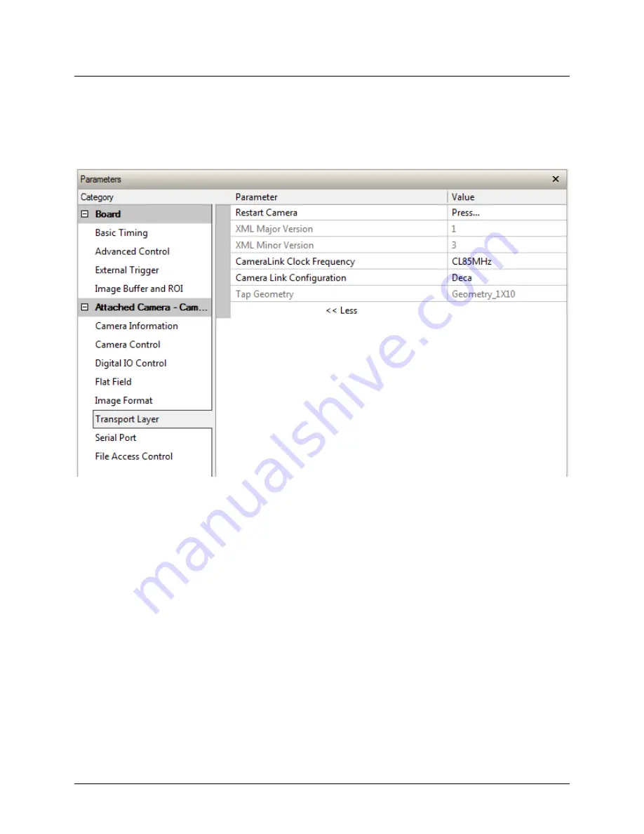
Transport Layer Control Category 

Parameters in gray are read only, either always or due to another parameter being disabled. 
Parameters in black are user set in CamExpert or programmable via an imaging application.   
Features listed in the description table but tagged as 

Invisible

 are usually for Teledyne 

DALSA or third party software usage—not typically needed by end user applications.  


Summary of Contents for P4-CC-08K03T-01-R

Page 1: ...Piranha4 8K Color Cameras P4 CC 08K03T 01 R sensors cameras frame grabbers processors software vision solutions 03 032 20274 01 www teledynedalsa com ...

Page 2: ...manufactures and markets digital imaging products and solutions in addition to providing wafer foundry services Teledyne DALSA Digital Imaging offers the widest range of machine vision components in the world From industry leading image sensors through powerful and sophisticated cameras frame grabbers vision processors and software to easy to use vision appliances and custom vision modules Contact...

Page 3: ... STEPS OVERVIEW 18 1 Install and configure frame grabber and software 18 2 Connect Camera Link and power cables 18 3 Establish communicating with the camera 18 4 Operate the camera 18 STEP 1 INSTALL AND CONFIGURE THE FRAME GRABBER AND SOFTWARE 19 Install frame grabber 19 Install Sapera LT and CamExpert GUI 19 STEP 2 CONNECT DATA TRIGGER AND POWER CABLES 19 INPUT OUTPUT CONNECTORS AND LED 19 Data c...

Page 4: ...RY 43 Camera information feature descriptions 44 Camera configuration selection dialog 47 Camera power up configuration 47 User set configuration management 47 CAMERA CONTROL CATEGORY 48 Camera control feature descriptions 48 Digital I O control feature descriptions 52 FLAT FIELD CATEGORY 54 Flat field control feature description 54 IMAGE FORMAT CONTROL CATEGORY 56 Image format control feature des...

Page 5: ...W 83 Supported Sapera LT 83 PROGRAMMING DECA MODE 83 PROGRAMMING FULL MODE 86 APPENDIX F CAMERA FRAME GRABBER COMMUNICATION 88 Setting up communication between the camera and the frame grabber 88 APPENDIX G ERROR AND WARNING MESSAGES 90 Hardware status under Camera Information 90 GenCP error code 90 EC FCC DECLARATION 92 STANDARD CONFORMITY 92 CE CONFORMITY 92 FCC CONFORMITY 92 ROHS CONFORMITY 92 ...

Page 6: ...lcohol To clean the surface of the camera housing use a soft dry cloth To remove severe stains use a soft cloth dampened with a small quantity of neutral detergent and then wipe dry Do not use volatile solvents such as benzene and thinners as they can damage the surface finish Further cleaning instructions are below Though this camera supports hot plugging it is recommended that you power down and...

Page 7: ... control and integrate Programmable features include exposure control flat field correction and gain settings The Piranha4 camera is ideal for the inspection of printing printed circuit board solar cell film and large format webs Key Features CMOS trilinear color line scan sensor 8k pixel resolution 3 x 8192 RGB 7 5 µm x 7 5 µm pixels Line rates up to 33 kHz x 3 24 bits RGB Programmability Camera ...

Page 8: ...e from third party vendors Camera Performance Specifications Table 4 Camera Performance Specifications Characteristics Typical Value Unit Sensor Characteristics at Maximum Pixel Rate Resolution 8192 x 3 RGB Pixels Pixel size square 7 5 x 7 5 µm Line rate maximum 33 x 3 kHz Radiometric Performance at Maximum Pixel Rate and Minimum Camera Gain Bit depth 3 x 8 Bits Response non linearity 1 PRNU HF Ma...

Page 9: ...storage and operation 15 to 85 relative non condensing MTBF mean time between failures 100 000 hours typical field operation Functionality Programmable via GenICam Control Interface Analog Gain Up to 12 x1 to x4 dB Offset Black Level 256 to 256 DN 8 bits Trigger Mode Internal and External Triggered Timed or Full Exposure Mechanical and Electrical Interface Size w x h x l 80 x 80 x 40 1 mm Weight 2...

Page 10: ...ax defined by the GenApi module of the GenICam specification The camera uses the GenICam Generic Control Protocol GenCP V1 0 to communicate over the Camera Link HS command lane For more information see www genicam org Sensor Responsivity and QE Spectral Responsivity The responsivity graph illustrates the sensor s response to different wavelengths of light excluding lens and light source characteri...

Page 11: ...2 Trilinear Quantum Efficiency 0 200000 400000 600000 800000 1000000 1200000 350 450 550 650 750 850 950 Responsivity e uJ cm 2 wavelength nm Responsivity row 27 row 28 row 29 0 10 20 30 40 50 60 70 350 450 550 650 750 850 950 FFQE wavelength nm Total Quantum Efficiency row 27 row 28 row 29 ...

Page 12: ...sures Line shift can also be disabled However this is only correct when the object pixel size is square i e the distance moved by the object for one EXSYNC period is equal to the width of the object pixel In some applications it may not be possible to achieve a square object pixel as fine adjustment of the lens magnification and or the distance moved for each EXSYNC period is not possible This sce...

Page 13: ...xample 1 Target speed adjusted for square pixels Example 2 Target running slower than example 1 same EXSYNC trigger frequency Example 3 Target running faster than example 1 same EXSYNC trigger frequency ...

Page 14: ...s not show up Figure 4 Image with Horizontal Color Alignment Issues Using the camera s Parallax Correction feature the optical magnification for each line is adjusted such that colors can be lined up at the extreme ends of the image without affecting the center Activate the feature Image Distortion Correction Mode imageDistortionCorrectionMode Active By tuning the feature Image Distortion Correcti...

Page 15: ...ection accommodates an object direction change on a web and allows you to mount the camera upside down Note The example here assumes the use of a lens which inverts the image Figure 7 Object Movement and Camera Direction Example with a Lens ...

Page 16: ...Mechanicals Figure 8 Camera Mechanicals ...

Page 17: ...ed light can be problematic with halogen light sources but is not an issue with white LED sources When infrared light is present with this camera color fidelity is reduced To prevent infrared from distorting the images you scan use an IR cut off filter such as a BG 38 on the lens ...

Page 18: ...er then you will need to install one Follow the manufacturer s installation instructions A GenCP Generic Control Protocol compliant XML device description file is embedded within the camera firmware allowing GenCP compliant applications to know the camera s capabilities immediately after connection Installing SaperaLT gives you access to the CamExpert GUI a tool that supports GenCP compliant devic...

Page 19: ... and comes bundled with SaperaLT Using CamExpert is the simplest and quickest way to send commands to and receive information from the camera Camera Link Environment These cameras implement the Camera link specification which defines the device capabilities The Camera link XML device description file is embedded within the camera firmware allowing Camera link compliant applications to recognize th...

Page 20: ...ld 14 14 inner shield 2 25 Y0 2 25 X0 15 12 Y0 15 12 X0 3 24 Y1 3 24 X1 16 11 Y1 16 11 X1 4 23 Y2 4 23 X2 17 10 Y2 17 10 X2 5 22 Yclk 5 22 Xclk 18 9 Yclk 18 9 Xclk 6 21 Y3 6 21 X3 19 8 Y3 19 8 X3 7 20 100 ohm 7 20 SerTC 20 7 terminated 20 7 SerTC 8 19 Z0 8 19 SerTFG 21 6 Z0 21 6 SerTFG 9 18 Z1 9 18 CC1 22 5 Z1 22 5 CC1 10 17 Z2 10 17 CC2 23 4 Z2 23 4 CC2 11 16 Zclk 11 16 CC3 24 3 Zclk 24 3 CC3 12 ...

Page 21: ... internally using the GenICam features The external control signal EXSYNC is optional and enabled through the user interface This camera uses the falling edge of EXSYNC to start the exposure period The EXSYNC signal tells the camera when to integrate the image followed by the readout It can be either an internally generated signal by the camera or it can be supplied externally via the serial inter...

Page 22: ... optimum performance WARNING When setting up the camera s power supplies follow these guidelines Apply the appropriate voltages Protect the camera with a 2 amp slow blow fuse between the power supply and the camera Do not use the shield on a multi conductor cable for ground Keep leads as short as possible in order to reduce voltage drop Use high quality supplies in order to minimize noise Note If ...

Page 23: ...be shown 3 Select the frame grabber device by clicking on the name Note The first time you set up the camera you will need to establish a communication link between the camera and frame grabber Instructions are available here Appendix F Camera Frame Grabber Communication Connect to the camera 1 Start a new Sapera CamExpert application or equivalent Camera Link compliant interface by double clickin...

Page 24: ...pgrade the camera s software An important component of CamExpert is its live acquisition display window which allows immediate verification of timing or control parameters without the need to run a separate acquisition program For context sensitive help click on the button then click on a camera configuration parameter A short description of the configuration parameter will be shown in a popup Cli...

Page 25: ...Piranha4 8k Color Camera User s Manual 25 Teledyne DALSA 03 032 20274 00 CamExpert panes Figure 12 CamExpert s Camera Control Window ...

Page 26: ... changing all acquisition parameters supported by the acquisition device CamExpert displays parameters only if those parameters are supported by the installed device This avoids confusion by eliminating parameter choices when they do not apply to the hardware in use Display pane Provides a live or single frame acquisition display Frame buffer parameters are shown in an information bar above the im...

Page 27: ... line column profile during live acquisition or in a still image Output Message pane Displays messages from CamExpert or the device driver The camera is now ready to retrieve a test pattern Select Image Format Control Test Pattern and choose one of the following available test images 0 Off Sensor Video 1 Grey Horizontal Ramp 2 White 3 Grey Pattern 4 Black 5 Grey Vertical Ramp At this point you are...

Page 28: ...stem Gain 1x White balanced gains all set to 1x Color correction parameters set to neutral values Corrected using an 80 mm lens and a magnification of 0 8 Check Camera and Sensor Information Camera and sensor information can be retrieved via a controlling application for example the CamExpert GUI shown in the following examples Parameters such as camera model firmware version sensor characteristic...

Page 29: ...temperature issue remove power wait for the camera to cool down and fix the temperature issue by improving your cooling strategy You may then restart the camera Saving and Restoring Camera Settings The parameters used to select load and save user sets are grouped together under the Camera Information set of features There are 4 user sets available and one factory set Camera Information Parameter C...

Page 30: ...an be saved thereby becoming the user setting using the User Set Save parameter A previously saved user setting User Set 1 to 4 or the factory settings can be restored using the User Set Selector and User Set Load parameters Either the Factory or one of the User settings can be saved as the Default Setting by selecting the set in the User Set Default Selector The chosen set automatically saves as ...

Page 31: ...ipped with the same settings as the factory set The command User Set Save saves the current settings to non volatile memory as a User Set The camera automatically restores the last saved user settings when it powers up To restore the last saved user settings select the User Set parameter you want to restore and then select the User Set Load parameter Factory Settings The factory setting is the cam...

Page 32: ...n be an internal timer signal free running mode or an external trigger signal The exposure duration can be programmable such as the case of an internal timer or maximum In the latter case the camera will maximize the exposure duration for the programmed line rate The camera can grab images in one of three ways You determine the three imaging modes using a combination of the Exposure Mode parameter...

Page 33: ...sure Mode Timed 2 Internally Programmable Line rate and Maximum Exposure Time Line rate can be adjusted When setting the line rate exposure time will automatically adjust to accommodate the new line rate Note The camera will not set line periods shorter than the readout period GenICam parameters to set I O Controls Trigger Mode Off Sensor Control Exposure Mode Maximum 3 External Line Rate Programm...

Page 34: ...ternal Trigger On Maximum exposure CC1 rising edge triggers start of internal exposure 4 External Trigger On Internal Exposure Control CC1 Rising edge triggers start of internal exposure Note minimum exposure time is 2 6 µs 1 If Exposure time 14 1 µs CC1 to Exposure start 4 1 µs 14 1 Exposure time 2 If Exposure time 14 1 µs CC1 to Exposure start 4 1 µs Figure 17 Exposure Modes ...

Page 35: ... the camera will continue to output data at its maximum line rate of 33 kHz Though no image artefacts associated with over speed will occur you may notice that under over speed conditions the image will appear compressed and the apparent distance travelled will be reduced Camera Control Parameter Description Line Rate in Hz Camera line rate in a range from 0 Hz to 33 KHz This feature is only avail...

Page 36: ...re Time To set the camera s exposure time use the Exposure Time parameter a member of the Sensor Controls set This feature is only available when the Exposure Mode parameter is set to Timed The allowable exposure range is dependent on the value of the internal line rate GenICam parameters Sensor Controls Exposure Time Timed Exposure Mode 2 6 µs to LinePeriod 2 5 µs Control Gain and Black Level The...

Page 37: ...ttern Black Grey Vertical Ramp Set Baud Rate The baud rate sets the speed in bits per second bps of the serial communication port and is available as part of the Serial Port Control parameters Serial Port Control Action Parameter Options Control the baud rate used by the camera s serial port Baud Rate 9600 factory default 19200 57600 115200 230400 Note During connection CamExpert automatically set...

Page 38: ...the expense of lower image resolution This camera provides only 1 x 1 pixel binning format Camera Direction Control Found in the I O Control Direction Control set of features Direction Control Parameter Description Sensor Scan Direction This command lets you select the Internal direction control Use this feature to accommodate object direction change on a web and to mount the camera upside down Ca...

Page 39: ...camera and puts in the default settings including a 9600 baud rate Calibrating the Camera Important Note to ensure best results the conditions under which you calibrate the camera e g temperature and illumination should be as close to the actual operating conditions as possible Figure 18 Flat Field Calibration in CamExpert Overview The following diagram and accompanying description explain the cam...

Page 40: ...th ColorChecker the camera should have been calibrated with a white reference in place of the Gretag Macbeth ColorChecker and color correction must be turned off The calibration process will ensure the camera output is uniform and white balanced 5 A single overall system gain is applied equally to all three colors It will therefore not cause color distortion when changed 6 A factory setting for wh...

Page 41: ...rs should be at the target value white balance gains will have been adjusted to suit the cameras optimum setup for a balanced white output and the correction coefficient will be enabled The system gain will remain as originally set The coefficient and gain parameters timing and control configuration etc can be stored in any one of eight user sets and automatically retrieved at power up or by user ...

Page 42: ... 1 This feature may not be of use to many users as the camera already subtracts true dark current but it may be useful for some to provide a per pixel offset correction 2 Default value is 0 DN for each pixel flatfieldCalibrationPRNU 1 Use flatfieldCorrectionAlgorithm to calculate the per pixel gain to achieve the specified target output 2 Default 1x 2 Contrast Enhancement The offset and gain featu...

Page 43: ... Parameters such as camera model firmware version etc are read to uniquely identify the connected P4 device These features are typically read only The Camera Information Category groups information specific to the individual camera In this category the number of features shown is identical whether the view is Beginner Expert or Guru Features listed in the description table but tagged as Invisible ...

Page 44: ...Standard Features Naming Convention SFNC not shown The Device Version number represents the camera software functional group not a firmware revision number Display Name Feature Description Device Version View Model DeviceModelName Displays the device model name RO 1 00 Beginner Vendor DeviceVendorName Displays the device vendor name RO 1 00 Beginner Serial Number DeviceID Displays the device s fac...

Page 45: ... make active on camera power up or reset The camera configuration sets are stored in camera non volatile memory RW 1 00 Beginner Factory Setting Default Load factory default feature settings UserSet1 UserSet1 Select the user defined configuration UserSet 1 as the Power up Configuration UserSet2 UserSet2 Select the user defined configuration UserSet 2 as the Power up Configuration UserSet3 UserSet3...

Page 46: ... by the user Current User Set UserSetSelector Points to which user set 1 4 or factory set that is loaded or saved when the UserSetLoad or UserSetSave command is used 1 00 Beginner Load Configuration UserSetLoad Loads the camera configuration set specified by the User Set Selector feature to the camera and makes it active W 1 00 Beginner Save Configuration UserSetSave Saves the current camera confi...

Page 47: ...ation state to load on power up see feature UserSetDefaultSelector The user chooses from one factory data set or one of two possible user saved states User set configuration management The second drop list allows the user to change the camera configuration any time after a power up see feature UserSetSelector To reset the camera to the factory configuration select Factory Setting and click Load To...

Page 48: ...ed Parameters in black are user set in CamExpert or programmable via an imaging application Camera control feature descriptions The following table describes these parameters along with their view attribute and minimum camera firmware version required Additionally the firmware column will indicate which parameter is a member of the DALSA Features Naming Convention DFNC versus the GenICam Standard ...

Page 49: ...ScanDirection Forward Reverse ExternallyControlled Sets the scan direction configuration Direction of the scan is Forward Direction of the scan is Reverse Direction of the scan is defined by CC3 CC3 0 Forward CC3 1 Reverse 1 00 Beginner Offset BlackLevel Controls the black level as an absolute physical value This represents a DC offset applied to the video signal in DN digital number units 1 00 Be...

Page 50: ...rrentUserColourSet Indicates which user set is currently in use RO 1 00 Beginner Color Transformation Value Selector ColorTransformationValueSele ctor Gain00 Gain01 Gain02 Gain10 Gain11 Gain12 Gain20 Gain21 Gain22 Allows the user to manually adjust correction value in the matrix Red Green Blue Red Gain00 Gain01 Gain02 Green Gain10 Gain11 Gain12 Blue Gain20 Gain21 Gain22 White LED matrix Red Green ...

Page 51: ...hm imageDistortionCorrectionAlgo rithm Parallax Correction RO 1 00 Beginner Image Distorition Parallax Correction Pixel Stretch imageDistortionParallaxCorrec tionPixelStretch Value entered indicates the number pixels to be shifted to correct the color alignment between 4 0 to 4 0 by step of 0 1 1 00 Beginner ...

Page 52: ... the minimum camera firmware version required Additionally the firmware column indicates which parameter is a member of the DALSA Features Naming Convention DFNC versus the GenICam Standard Features Naming Convention SFNC not shown The Device Version number represents the camera software functional group not a firmware revision number Display Name Feature Description Device Version View Trigger Se...

Page 53: ...s Wait For Trigger StatusWaitForT rigger Bit0 of Hardware status 1 if no trigger identified for more than 1 second 1 00 Beginner Status Trigger Too Fast StatusTriggerT ooFast Bit1 of Hardware status 1 if missed triggers identified trigger running too fast for camera 1 00 Beginner ...

Page 54: ...Expert or programmable via an imaging application Features listed in the description table but tagged as Invisible are usually for Teledyne DALSA or third party software usage not typically needed by end user applications Flat field control feature description The following table describes these parameters along with their view attribute and minimum camera firmware version required Additionally th...

Page 55: ...Calibrate PRNU flatfieldCalibrationPRNU Initiates the PRNU or Flatfield process 1 00 Beginner FFC Bank Selector FFCBankSelector Factory User1 User2 User3 User4 Allows the user to select between the factory or 4 user FFC sets Factory loaded FFC User generated FFC User generated FFC User generated FFC User generated FFC 1 00 Beginner Load FFC from bank FFCSetLoadFromBank Loads the FFC set specified ...

Page 56: ...rning FFC or balance overflow StatusWarningFfcOrBalanceO vf 0 1 Status register after FFC calculation RO No overflow during FFC Overflow during FFC 1 00 Beginner Image Format Control Category The Image Format controls as shown by CamExpert group parameters used to configure camera pixel format image cropping and test pattern Parameters in gray are read only either always or due to another paramete...

Page 57: ...ided by the device manufacturer 1 00 Beginner DFNC Off Selects sensor video to be output from sensor Grey Horizontal Ramp Selects a horizontal grey scale White Selects a blank white pattern Grey Pattern Selects a blank grey pattern Black Selects a blank black pattern Grey Vertical Ramp Selects a vertical grey scale Line Mirroring ReverseX 1 00 Beginner Off On Video output in normal order Video out...

Page 58: ...e read only either always or due to another parameter being disabled Parameters in black are user set in CamExpert or programmable via an imaging application Features listed in the description table but tagged as Invisible are usually for Teledyne DALSA or third party software usage not typically needed by end user applications ...

Page 59: ...a DeviceReset Used to restart the camera warm reset 1 00 Beginner XML Major Version DeviceManifestXMLMajorVersio n Together with DeviceManifestXMLMinorVersio n specifies the GenICam feature description XML file version RO 1 00 Beginner XML Minor Version DeviceManifestXMLMinorVersio n Together with DeviceManifestXMLMajorVersio n specifies the GenICam feature description XML file version RO 1 00 Beg...

Page 60: ...ort control feature descriptions The Device Version number represents the camera software functional group not a firmware revision number Display Name Feature Description View Baud Rate DeviceSerialPortBaudRate Sets the baud rate used by the selected device s serial port Available baud rates are device specific 1 00 Beginner Baud_9600 Baud_19200 Baud_38400 Baud_57600 Baud_115200 Baud rate is 9600 ...

Page 61: ...1 00 Beginner One Use 1 stop bit File Access Control Category The File Access control in CamExpert allows the user to quickly upload various data files to the connected camera The supported data files are for firmware updates flat field coefficients LUT data tables and a custom image for use as an internal test pattern Features listed in the description table but tagged as Invisible are usually fo...

Page 62: ... operation executed by FileOperationExecute Read Read Select the Read operation executed by FileOperationExecute Write Write Select the Write operation executed by FileOperationExecute Delete Delete Select the Delete operation executed by FileOperationExecute File Operation Execute FileOperationExecute Executes the operation selected by File Operation Selector on the selected file 1 00 Guru File O...

Page 63: ...camera model File Operation Result FileOperationResult Displays the file operation result For Read or Write operations the number of successfully read written bytes is returned RO 1 00 Guru File Size FileSize Represents the size of the selected file in bytes 1 00 Guru File Access via the CamExpert tool 1 Click on the Setting button to show the file selection menu 2 From the Type drop menu select t...

Page 64: ...t firmware changes require a device reset command from the Camera Information Controls and additionally CamExpert should be shut down and restarted after a reset Download a list of camera parameters For diagnostic purposes you may want to download a list of all the parameters and values associated with the camera 1 Go to File Access Control 2 Click on Settings 3 In the Type drop down box select Ca...

Page 65: ...Piranha4 8k Color Camera User s Manual 65 Teledyne DALSA 03 032 20274 00 ...

Page 66: ...fication Figure 21 Serial DLL hierarchy as mentioned in the Camera Link Specification 1 Cycle power to the camera by either a issuing the reset camera command rc or b powering the camera OFF and then ON 2 Load the ASCII interface using 9600 baud 8 data bits no parity 1 stop bit no flow control Receive CR LF Transmit CR Local echo 3 Wait for a stable status LED color green or red before proceeding ...

Page 67: ...aracter may look like this The camera responds to a simple ASCII based protocol A carriage return CR ends each command Example to return the current detector settings gcp CR A complete list of the available detector commands their format and parameters can be displayed by sending the help h command Port configuration Baud 9 600 Bits 8 Parity None Stop bits 1 Flow Control None Echo typed characters...

Page 68: ...scription Calibrate user FPN dark flat field coefficients Full Name Camera Link Mode Mnemonic clm Argument s Mode 0 Base 1 Medium 2 Full 3 Deca Description Camera Link Mode Full Name Camera Link Speed Mnemonic cls Argument s Frequency 0 85 MHz 1 80 MHz 2 60 MHz 3 42 5 MHz Description Camera Link clock frequency Full Name Calibrate Flatfield Mnemonic cpa Argument s Start 1 Description Calibrate use...

Page 69: ...ain11 5 cgb Gain12 6 cbr Gain20 7 cbg Gain21 8 cbb Gain22 Integer Value From 256 gain 4 to 255 gain 3 984375 by step of 0 015625 1 64 Description Color Transformation Matrix Full Name Flatfield Mode Mnemonic ffm Argument s Mode 0 Disable use of user FPN and PRNU flat field correction coefficients 1 Enable use of user FPN and PRNU flat field correction coefficients Description Set flat field mode N...

Page 70: ...or blue 1024 Color Matrix Selector 4 Color Correction Matrix 49 25 10 25 79 10 34 15 113 Mirroring Mode Off Camera Link frequency 85MHz Camera Link mode 8bits RGB_Base 3Taps Pixel Format 8K TriLinear RGB USER Full Name Get Value Mnemonic get Argument s parameter Description The get command displays the current value s of the feature specified in the string parameter Using this command will be easi...

Page 71: ...357ns smm Mirroring Mode 0 Off 1 On spf Pixel Format 0 RGB8 ssa Set Spatial Alignment 0 disabled 1 0 5 line 2 1 line 3 1 5 line 4 2 lines ssb Offset 4096 to 4095 in 12 bit DN ssf Internal Line Rate returns line rate in Hz ssg Gain 7 lines 0 Preamp 1 System 2 contrast expansion 3 contrast offset 4 red 5 green 6 blue fixed point numbers stm Trigger Mode 0 Off internal 1 On external sui Set User ID M...

Page 72: ...5200 scd Direction 0 Forward 1 Reverse 2 CC3 signal sem Exposure Mode 0 Off 1 On set Exposure Time Integer 32 bits step of 6 357ns sha Set horizontal alignment From 40 4 pixels to 40 4 pixels shm Set horizontal alignment mode 0 Off 1 Active smm Mirroring 0 Off 1 On spf Pixel Format 0 8k pixels RGB true color ssa Set Spatial Rebuild 0 Disabled 1 0 5x 2 1x 3 1 5x 4 2x ssb Offset 4096 to 4095 step 1 ...

Page 73: ...ne Notes Full Name Set Baud Rate Mnemonic sbr Argument s Baud rate 9600 19200 38400 57600 115200 Description Set baud rate Notes Send command and then change speed of HyperTerminal Full Name Direction Mnemonic scd Argument s Direction 0 Forward 1 Reverse 2 External controlled by CC3 signal Description Set sensor scan direction Notes Full Name Exposure Mode Mnemonic sem Argument s Mode 0 Internal 1...

Page 74: ...0 to 40 by step of 1 unit is 1 10 pixel Description The value entered will stretch shrink the sensor red and green lines to align the colors Notes Full Name Set Horizontal Alignment Mode Mnemonic shm Argument s Selector 0 Off 1 Active Description Enable the horizontal correction Notes Full Name Mirroring Mnemonic smm Argument s Mode 0 Off 1 Image is flipped on the vertical axis Description Set mir...

Page 75: ...in order to set the line delay Values entered must be between 0 and 4 Decimal places are not valid Full Name Offset Mnemonic ssb Argument s Offset 8 bit 4096 to 4095 step 1 in DN12b Description Set offset Notes 4096 in DN12b correspond to 256 in DN8b Full Name Internal Line Rate Mnemonic ssf Argument s Line rate 1 to 33 000 Hz Description Set internal line rate Notes Line time Exposure time 2 500 ...

Page 76: ...cal ramp Description Select test pattern Notes Full Name Default User Set Mnemonic usd Argument s Set selector 0 Factory set 1 4 User sets Description Select user set to load when camera is reset Notes The settings include all those listed by the GCP command plus the user FPN coefficients user PRNU coefficients and color correction matrix Full Name Load User Set Mnemonic usl Argument s Set selecto...

Page 77: ...Argument s Set selector 1 to 4 Description Save user set Notes Saves all the current settings listed by the GCP command plus the user FPN coefficients user PRNU coefficients and color correction matrix Full Name Temperature Mnemonic vt Argument s Description Display internal temperature in degrees Celsius Notes ...

Page 78: ...z line rate using Camera Link Deca mode but it may be easier to start your evaluation using the medium mode Set your Camera Link frame grabber up to receive the standard RGB medium mode 2 Communicating with the Camera The color camera is designed to power up with a GenICam compliant interface CamExpert provides an easy to use GUI that can be used to set up and evaluate the camera The camera also c...

Page 79: ...e exposure time using the set command Ensure that the exposure time period is not greater than the period of the line rate minus 2 5 µsec The camera will indicate an error if you select an exposure time that is too long The minimum exposure time is 2 6 µsec Set your camera direction using the scd command Refer to the Camera direction diagram in this manual for a definition of forward and reverse 5...

Page 80: ...n completion of the cpa command you should see an image from the camera that is white balanced with all three colors at the target level you set You are now ready to evaluate the image quality of the P4 color camera under your operating conditions 6 Improving Your Color Image The color response of the P4 color camera is quite good even when using white LED s without color correction A white LED co...

Page 81: ...e and to avoid introducing oily residues avoid touching the sensor Scratches diffract incident illumination When exposed to uniform illumination a sensor with a scratched window will normally have brighter pixels adjacent to darker pixels The location of these pixels will change with the angle of illumination An important note on window blemishes When flat field correction is performed window clea...

Page 82: ...ng an ionized air gun Place the sensor under the microscope at a magnification of 5x to determine the presence of any remaining contamination Clean the contamination on the sensor using one drop of cleaning fluid on a swab Wipe the swab from left to right or right to left but only in one direction Do this in an overlapping pattern turning the swab after the first wipe and with each subsequent wipe...

Page 83: ...re images with the Piranha4 color camera under RGB 9 1 Deca mode to achieve a 68 5 KHz line rate and under RGB 6 2 Full mode to achieve a 55 KHz line rate Supported Sapera LT Sapera 7 10 or later is required Programming Deca Mode The RGB 9 1 Deca mode uses Camera Link 10 tap 8 bit mode to achieve RGB formatting Below is the Camera Link port assignment of Deca mode ...

Page 84: ...s a feature to share buffer components between two SapBuffer objects Buffer type may Red 1 D0 D7 Blue 1 D0 D7 Green 1 D0 D7 Red 2 D0 D7 Blue 2 D0 D7 Green 2 D0 D7 Red 3 D0 D7 Blue 3 D0 D7 Green 3 D0 D7 Red 4 D0 D7 Blue 4 D0 D7 Green 4 D0 D7 Red 5 D0 D7 Blue 5 D0 D7 Green 5 D0 D7 Red 6 D0 D7 Blue 6 D0 D7 Green 6 D0 D7 Red 7 D0 D7 Blue 7 D0 D7 Green 7 D0 D7 Red 8 D0 D7 Blue 8 D0 D7 Green 8 D0 D7 Red...

Page 85: ...m_Buffers m_Buffers new SapBufferWithTrash NUMBUFFERS m_Acq Call Create for acquisition buffer m_Buffers Create Declare SapBuffer object which shares buffer components with the acquisition buffer SapBuffer m_ViewBuffers int width height i void pData NUMBUFFERS for i 0 i NUMBUFFERS i m_Buffers GetAddress i pData i width m_Buffers GetWidth height m_Buffers GetHeight m_ViewBuffers new SapBuffer NUMBU...

Page 86: ...r to correctly format the image for processing and display purposes frame grabbers need to support RGB 6 2 mode natively Until then here are some workarounds using Sapera LT Notice to support this pixel format in memory the buffer must be set to RGB 24 bit packed All Sapera demo and example programs extract the create acquisition buffer type from the associated camera configuration files Until the...

Page 87: ...he same buffer contents as the SapFormatRGBR888 Sample code Assuming acquisition buffer is declared as below define NUMBUFFERS 8 SapBuffer m_Buffers m_Buffers new SapBufferWithTrash NUMBUFFERS m_Acq Call Create for acquisition buffer m_Buffers Create Declare SapBuffer object which shares buffer components with the acquisition buffer SapBuffer m_ViewBuffers int width height i void pData NUMBUFFERS ...

Page 88: ...ation manual 2 Install Sapera LT and the Teledyne DALSA frame grabber driver 3 Connect the camera to the frame grabber refer to the camera installation manual 4 Power up the camera and wait until the status LED is solid green 5 Run the Sapera Configuration utility and select the frame grabber serial port connected to the camera Set Teledyne DALSA camera detection to Automatic Detection and Baud ra...

Page 89: ...ab select CameraLink Medium Color RGB 1 8 Modify the camera and frame grabber parameter settings as required At present when using GenCP cameras the camera and frame grabber parameters must be adjusted separately Test the image acquisition by clicking the Grab button 9 Save the frame grabber configuration to a new ccf file ...

Page 90: ... occur in the camera one or more these flags could be set Some of these flags set will result in the status light turning red Definition Flag No trigger during more than 1s Bit0 Trigger too fast Bit1 SNS Pattern failed Bit2 Overflow occurred during FFC calibration Bit8 Underflow occurred during FFC calibration Bit9 Calibration error Bit10 CC3 scrolling direction 0 Fwd 1 Rev Bit11 Initialization in...

Page 91: ...read only register 0x8005 GENCP_BAD_ALIGNMENT Attempt to access registers with an address which is not aligned according to the underlying technology 0x8006 GENCP_ACCESS_DENIED Attempt to read a non readable or write a non writable register 0x8007 GENCP_BUSY The command receiver is currently busy 0x800B GENCP_MSG_TIMEOUT Timeout waiting for acknowledge 0x800E GENCP_INVALID_HEADER The header of the...

Page 92: ...cluding interference that may cause undesired operation EN55024 This equipment has been tested and found to comply with the limits for Class A digital device pursuant to part 15 of the FCC rules These limits are designed to provide reasonable protection against harmful interference when the equipment is operated in a commercial environment This equipment generates uses and can radiate radio freque...

Page 93: ...ha4 8k Color Camera User s Manual 93 Teledyne DALSA 03 032 20274 00 Revision History Revision Change Description Date 00 Initial release 28 June 2019 01 Flash memory specification added 32 Mbytes 9 July 2019 ...

Page 94: ...ration of Conformity 92 direction sensor shift 15 web movement 15 E environmental specifications 9 error and warning messages 90 exposure control 32 external frame rate programmable exposure time 33 internally controlled 33 exposure modes descriptions of 32 exposure time set 36 EXSYNC 21 F factory settings 28 filters 17 G Gain control 36 GUI overview 23 H humidity storage and operation 9 I image a...

Page 95: ... 10 revision history 93 S safety 6 Sapera 24 sensor controls 48 52 56 settings current 31 default 31 factory 28 31 loading 29 saving 29 user 31 setup overview 18 shift direction 15 size image 37 software required 8 specifications performance 8 storage temperature 9 T temperature verify 29 trigger modes 32 V voltage verify 29 ...

Reviews: