background image


116  

  Appendix A: GenICam Commands 

Linea HS Series Camera User's Manual   

Acquisition and Transfer Control Category 

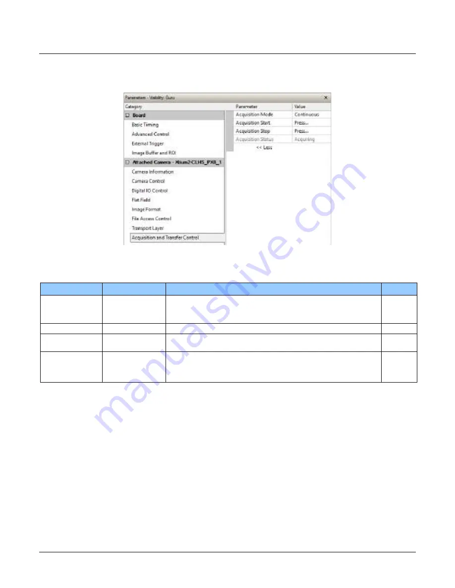
The Acquisition and Transfer controls, as shown by CamExpert, has parameters used to configure 
the optional acquisition modes of the device.  


Figure 59: Acquisition & Transfer Control Panel 

Acquisition and Transfer Control Feature Descriptions 

Display Name 

Feature 

Description 

View 

Acquisition Mode 

AcquisitionMode 

The device acquisition mode defines the number of frames to 

capture during an acquisition and the way it stops 

Beginner 

Continuous 

Continuous  Only continuous mode is currently available. 


Acquisition Start 

AcquisitionStart 

Commands the camera to start sending image data. (WO) 

Beginner 

Acquisition Stop 

AcquisitionStop 

Commands the camera to stop sending image data at the end of the 

current line (WO) 

Beginner 

Acquisition Status  AcquisitionStatus 

Reads the acquisition state.  

Beginner 

Acquiring 

Acquiring  Currently acquiring and sending image data. 


Not Acquiring 

NotAcquiring  Currently not acquiring or sending image data. 


Summary of Contents for Linea HS Series

Page 1: ...Linea HS Series Camera User s Manual Monochrome Color and Multifield TDI Line Scan sensors cameras frame grabbers processors software vision solutions 03 032 20296 01 Revision 01 www teledynedalsa com...

Page 2: ...ted States and other countries Windows Windows 7 Windows 8 are trademarks of Microsoft Corporation All other trademarks or intellectual property mentioned herein belong to their respective owners Docu...

Page 3: ...mory Size 19 Certification Compliance 19 SPECIFICATIONS MONOCHROME MODELS 20 Responsivity QE 20 Camera Input Power 22 SPECIFICATIONS COLOR MODEL 24 Responsivity QE 24 Camera Input Power 24 SPECIFICATI...

Page 4: ...nternal Trigger Mode 68 ESTABLISHING THE OPTIMAL RESPONSE 69 Exposure Control by Light Source Strobe 69 Image Response Uniformity Flat Field Calibration 72 Saving Loading a PRNU Set Only 73 Setting Cu...

Page 5: ...e Description 106 FILE ACCESS CONTROL CATEGORY 109 File Access Control Feature Descriptions 109 File Access via the CamExpert Tool 111 CLHS File Transfer Protocol 112 Upload File to Camera 113 Downloa...

Page 6: ...nical Drawing 39 Figure 23 CamExpert Frame Grabber Control Window 42 Figure 24 Camera I O Connectors CX4 left LC Fiber Optic right 44 Figure 25 12 pin Hirose Pin Numbering 45 Figure 26 GPIO cable acce...

Page 7: ...103 Figure 55 Image Format Panel 106 Figure 56 File Access Control Panel 109 Figure 57 File Access Control Tool 111 Figure 58 File Upload Completed Message Box 111 Figure 59 Transport Layer Panel 114...

Page 8: ...lm and large format web materials Monochrome Models Part Number Description HL FM 04K30H 00 R 4096 x 192 pixels maximum line rate of 300 kHz 5 m x 5 m pixel size monochrome HDR output Camera Link HS L...

Page 9: ...hree images captured by separate TDI arrays Depending on the light sources used narrowband filters may be needed at the light sources This new technology significantly improves the inspection speeds a...

Page 10: ...correction High dynamic LUT mode Resolution Monochrome Models 4K 8K 13K 16K 32k pixel resolution Color and Mulitifield Model 16K pixel resolution Programmability Multiple areas of interest for data re...

Page 11: ...ls 400 kHz mono 200 kHz x 2 HDR 5 0 x 5 0 m Camera Link HS CX4 HL FM 13K18H 00 R 13056 x 192 128 64 180 kHz mono 90 kHz x 2 HDR 5 0 x 5 0 m Camera Link HS LC fiber optic HL HM 13K30H 00 R 13056 x 192...

Page 12: ...T Teledyne DALSA Xtium2 CLHS PX8 HR OR A8S0 HX870 HL HM 32K40S Other compatible frame grabbers may be available from third party vendors Required for custom patent pending pixel processing HL HM 32K40...

Page 13: ...ctors and Mechanicals Control Data Interface Camera Link HS CX4 or LC Power 12 V to 24 V DC Hirose 12 pin circular Operating Temp 0 C to 65 C front plate temperature Optical Interface Sensor to Camera...

Page 14: ...mm 140 5 mm 78 6 mm Mass 500 g 1 2 kg 1 2 kg Optical Interface HL FM 04K30H HL FM 13K18H HL HM 13K30H Lens Mount M58 x 0 75 mm M90 x 1 mm M90 x 1 mm Performance 1 Notes Random Noise 0 2 DN rms 10 e T...

Page 15: ...ass 500 g 1 2 kg 500 g 1 2 kg Optical Interface HL FM 08K30H HL FM 16K15A HL HM 08K30H HL HM 16K30H Lens Mount M58 x 0 75 mm M90 x 1 mm M58 x 0 75 mm M90 x 1 mm Performance 1 Notes Random Noise 0 2 DN...

Page 16: ...HS CX4 Power 12 V to 24 V DC Hirose 12 pin circular Typical Power Dissipation 18 W 30 W Size Width Height Depth 76 mm 76 mm 85 mm 97 mm 140 5 mm 78 6 mm Cross Scan direction In Scan direction Along o...

Page 17: ...7 mm 140 5 mm 78 6 mm Cross Scan direction In Scan direction Along optical axis Mass 1 2 kg 1 2 kg Optical Interface HL HC 16k10T HL HF 16K13T Notes Lens Mount M90 x 1 mm M90 x 1 mm Performance 1 HL H...

Page 18: ...ectors and Mechanicals HL HM 32K40S Notes Typical Power Dissipation 28 W Size Width Height Depth 76 mm 97 mm 140 5 mm Cross Scan direction In Scan direction Along optical axis Mass 1 2 kg Optical Inte...

Page 19: ...Cameras 19 Flash Memory Size Table 10 Camera Flash Memory Size Camera Flash memory size All models 4 GByte Certification Compliance Table 11 Camera Certification Compliance Compliance See the Declarat...

Page 20: ...FM 04K30H 00 R HL FM 08K30H 00 R HL HM 08K30H 00 R HL HM 08K40H 00 R HL FM 13K18H 00 R HL HM 13K30H 00 R HL FM 16K15A 00 R HL HM 16K30H 00 R HL HM 16K40H 00 R Responsivity QE The following graphs show...

Page 21: ...s Manual Linea HS Series Cameras 21 The following graphs show the spectral Responsivity and QE from the main array 128 stages in 8 bit for 13k and 16k camera models Figure 2 13k and 16K Monochrome Mod...

Page 22: ...ng graphs detail the power vs input voltage for model HL HM and HL FM models Figure 3 Standard 4k and 8k Models Power vs Input Voltage Figure 4 Standard 13k and 16k Models Power Vs Input Voltage Test...

Page 23: ...Series Cameras 23 The following graphs detail the power vs input voltage for the HL HM 16K40H 00 R Figure 5 HL HM 16K40H 00 R Power Vs Input Voltage Test conditions Max line rate 400 kHz TDI Mode 128...

Page 24: ...wing specifications apply to the color Linea HS model HL HC 16K10T 00 R Responsivity QE The following graphs show the spectral Responsivity and QE 8 bit 1x gain Figure 6 Color Model Spectral Responsiv...

Page 25: ...Linea HS Series Camera User s Manual Linea HS Series Cameras 25 Figure 7 Color Model Power Vs Input Voltage Test conditions Max line rate 300 kHz Bit Mode 8 Black Level 31 Temperature Ambient...

Page 26: ...Manual Specifications Multifield Model The following specifications apply to the multifield Linea HS model HL HF 16K13T Responsivity QE The following graphs show the spectral Responsivity and QE 8 bit...

Page 27: ...as 27 Figure 9 Multifield Model QE Camera Input Power The following graph details the power vs input voltage for the camera Figure 10 Multifield Model Power Vs Input Voltage Test conditions Max line r...

Page 28: ...wing specifications apply to the super resolution Linea HS model HL HM 32K40S 00 R Responsivity QE The following graphs show the spectral responsivity and QE in 32k super resolution mode for 16k modes...

Page 29: ...as 29 Camera Input Power The following graphs detail the power vs input voltage for the HL HM 32K40S 00 R Figure 12 Super Resolution Model Power Vs Input Voltage Test conditions Max line rate 300 kHz...

Page 30: ...tely every 7 C For best performance Teledyne DALSA recommends recalibrating the dark flat field coefficients FPN at a stable operating temperature for more information of flat field correction refer t...

Page 31: ...Linea HS Series Camera User s Manual Linea HS Series Cameras 31 Figure 14 Line Period vs Dark Signal...

Page 32: ...ain system gain EOI offset EOI gain filter vertical binning horizontal binning LUT output video Figure 15 Digital data processing chain Supported Industry Standards GenICam The camera is GenICam compl...

Page 33: ...in the case of Linea HS camera the SFP modules are built into the camera Either one or both SFP modules can be used but using only one SFP fiber optic will sacrifice available bandwidth Figure 16 Line...

Page 34: ...factor fiber optic connector that uses a 1 25 mm ferrule half the size of a standard connector These cables are in wide use in the telecommunications industry and available in many lengths The distanc...

Page 35: ...he cable ends to improve speed and distance performance of the cable without sacrificing compatibility with standard electrical interfaces Camera Link HS cables can be bought from an OEM OEM cables ar...

Page 36: ...36 Linea HS Series Cameras Linea HS Series Camera User s Manual Mechanical Drawings Figure 18 HL FM 04K30H 00 R and HL FM 08K30H 00 R Mechanical Drawing...

Page 37: ...Linea HS Series Camera User s Manual Linea HS Series Cameras 37 Figure 19 HL HM 08K30H 00 R and HL HM 08K40H 00 R Mechanical Drawing...

Page 38: ...38 Linea HS Series Cameras Linea HS Series Camera User s Manual Figure 20 HL FM 13K18H 00 R and HL FM 16K15A 00 R Mechanical Drawing...

Page 39: ...Linea HS Series Camera User s Manual Linea HS Series Cameras 39 Figure 21 HL HM 13K30H 00 R HL HM 16K30H 00 R HL HM 16K40H 00 R and HL HF 16K10T 00 R Mechanical Drawing...

Page 40: ...ic discharging violent vibration and excess moisture To clean the device avoid electrostatic charging by using a dry clean absorbent cotton cloth dampened with a small quantity of pure alcohol Do not...

Page 41: ...mExpert is the camera interfacing tool supported by the Sapera library When used with the camera CamExpert allows a user to test all camera operating modes In addition CamExpert can be used to save th...

Page 42: ...vice is selected CamExpert will only show acquisition parameters for that device Optionally select a camera file included with the Sapera installation or saved previously Parameters pane Allows the vi...

Page 43: ...rigger Enabled click to send a single trigger command CamExpert display controls these do not modify the frame buffer data Stretch image to fit set image display to original size or zoom the image to...

Page 44: ...efore connecting power to the camera test all power supplies Protect the camera with a 3 amp slow blow fuse between the power supply and the camera Do not use the shield on a multi conductor cable for...

Page 45: ...1 4 6 7 12 11 3 2 10 8 9 5 Figure 24 12 pin Hirose Pin Numbering Table 13 12 pin Hirose Pin Assignment Pin Number Input Output Signal Details Notes 1 Power Ground 2 12 V to 24 V power 3 Output Line 3...

Page 46: ...V 10 K External Input Timing Reference Table 15 External Input Timing Reference Input Level Standard Max Input Frequency Min Pulse Width Input Current Maximum Signal Propagation Delay 60o C 3 3 V TTL...

Page 47: ...s Cameras 47 Mating GPIO Cable Assembly An optional GPIO breakout cable 12 pin Female Hirose to 13 Pos Euro Block is available for purchase from Teledyne DALSA under accessory number CR GENC IOP00 to...

Page 48: ...ready for data transfer to begin When the camera s LED state is steady green CamExpert will search for installed Sapera devices In the Devices list area on the left side of the window the connected f...

Page 49: ...ng with a static object and no encoder input is required Enable the camera to output a test pattern Use a frame grabber CamExpert instance to capture display and analyze the test pattern image to veri...

Page 50: ...e using pin 5 and pin 6 of the GPIO connector Use the Trigger Activation feature to select the edge that triggers the camera The options are Rising Edge Falling Edge or Any Edge When using Any Edge be...

Page 51: ...x 2 180 kHz 90 kHz x 2 HL HM 08K30H 00 R 300 kHz 150 kHz x 2 300 kHz 150 kHz x 2 HL FM 13K18H 00 R 180 kHz 90 kHz x 2 120 kHz 60 kHz x 2 HL HM 13K30H 00 R 300 kHz 150 kHz x 2 230 kHz 115 kHz x 2 HL FM...

Page 52: ...or all camera models is 10 Hz Scan Direction See the section Camera Control Category in Appendix A for GenICam features associated with this section and how to use them Related Feature sensorScanDirec...

Page 53: ...nea HS Series Camera User s Manual Camera Performance and Features 53 If blur occurs only in scan direction see below the scan direction is set incorrectly Figure 26 Image with incorrect scan directio...

Page 54: ...cs of the lens the direction of the objects motion is opposite to the image motion direction Some inspection systems require that the scan direction change at regular intervals For example scanning a...

Page 55: ...inea HS cameras The camera ensures the scan direction alignment of the lines by delaying the image data for each row a set amount of time as dictated by the scan direction The camera automatically adj...

Page 56: ...s Manual Standard and High Speed Models Dual Array Line Spacing 64 Lines 5 m pixel 128 Lines 5 m pixel Scan Direction Readout Readout 175 m gap equivalent to 35 lines 163 Line Correction Figure 29 Sta...

Page 57: ...l Camera Performance and Features 57 64 Lines 5 m pixel 128 Lines 5 m pixel Scan Direction Readout Readout 175 m gap equivalent to 35 lines 99 Line Correction Figure 30 Standard and High Speed Camera...

Page 58: ...nual Multifield Model Array Spacing 64 Lines 5 m pixel 128 Lines 5 m pixel Scan Direction Readout Readout gap of 35 lines 163 Line Correction 64 Lines 5 m pixel Readout 99 Line Correction gap of 35 li...

Page 59: ...d Features 59 64 Lines 5 m pixel 128 Lines 5 m pixel Scan Direction Readout Readout gap of 35 lines 64 Lines 5 m pixel Readout 99 Line Correction gap of 35 lines 163 Line Correction Figure 32 Standard...

Page 60: ...ffective pixel pitch super resolution image The multiple arrays are aligned automatically in the frame grabber using row spacing data provided by the camera 64 Lines 5 m pixel 128 Lines 5 m pixel Forw...

Page 61: ...ures 61 64 Lines 5 m pixel 128 Lines 5 m pixel Reverse Scan Direction 35 line gap 64 Lines 5 m pixel 35 line gap 81 923 mm 1 133 mm 99 Line Correction 163 Line Correction Readout Readout Readout Figur...

Page 62: ...calOffset alignmentMarkerHorizontalSpacing alignmentMarkerHorizontalOffset and alignmentMarkerBlack Use alignment markers to assist in aligning the camera to ensure that all sensor columns align verti...

Page 63: ...ciently large this may cause artifacts at the extremities of the image To correct for parallax pixels at lower magnification can be interpolated to provide the required resolution That is for lower ma...

Page 64: ...ect on Sensor Arrays Output For example with a sensor resolution of 8192 pixels if the lower magnification equivalent distance is 8185 pixels these pixels would be interpolated in other words stretche...

Page 65: ...ifferent modes 32k SR Detail Restored 32k SR Mapped TDI TDI Area mode and TDI Extended Area TDI Mode TDI mode is the default operating mode for the camera The camera combines multiple exposures of an...

Page 66: ...condary Array Stages 2 1 128 64 4 1 64 16 8 1 128 16 High Full Well High Full Well HFW mode sets both arrays at equal stage count providing an additional bit of output data Processing the upper bits N...

Page 67: ...subsequent user data processing Use this mode in the initial setup to evaluate whether your system benefits enough from the 32k SR operation and to avoid conflicts for your algorithms 32k SR Detail Re...

Page 68: ...eed Models Internal Trigger Rate Features TDI Mode Trigger Rate Feature Maximum TDI AcquisitionLineRate 400 kHz HDR HFW AcquisitionLineRate 200 kHz Area AcquisitionFrameRate 2 kHz Multi Area Acquisiti...

Page 69: ...to be achieved The camera s internal line rate generator and exposure control can be used for a stationary target Exposure Control by Light Source Strobe Relevant Features outputLineSource outputLine...

Page 70: ...er sensor response and data processing In addition an Exposure Active signal is generated and can be supplied to any of the GPIO outputs This allows triggering or timing external light sources The fol...

Page 71: ...tion Debouncer Debouncer Trigger Activation Input Line 1 Input Line 2 GPIO Connector Output Line Invert Output Line 3 GPIO Connector Output Delay Output Duration Output Line 4 Output Line 5 Output Lin...

Page 72: ...m structure Flat field calibration should be performed when the camera temperature has stabilized Flat field calibration will adjust all pixels to have the same value as the peak pixel value or target...

Page 73: ...coefficients and a LUT These three features let you save load just the PRNU coefficients Loading a complete user set takes approximately 1 second while loading only the user PRNU coefficients takes le...

Page 74: ...which can minimize the effects of dirt Note This filter is only capable of compensating for small occasional contaminants It will not overcome large features in a target s texture Flat Field Calibrat...

Page 75: ...hted average filters The 1 x 3 filter kernel uses 75 of the original pixel and 12 5 of the adjacent pixels 12 5 75 12 5 Figure 40 1 x 3 kernel The 1 x 5 filter kernel uses 50 of the original pixel and...

Page 76: ...by adjacent pixels are summed The camera supports 1x 2x and 4x horizontal and vertical binning Vertical binning is only available in TDI single plane mode Horizontal binning is achieved by summing adj...

Page 77: ...superfluous image data Eliminating unwanted image data that is visible in the camera s field of view reduces the amount of information the host computer needs to process This may result in an increas...

Page 78: ...where necessary Note AOI parameters can only be changed when image transfer to the frame grabber is stopped Refer to the Acquisition and Transfer Control Category in the appendix for details on stopp...

Page 79: ...rt X Coordinate EOI Width EOI Offset Gain Adjustment Pixel Value Figure 43 Enhancement of Interest EOIs are designed for applications where maximum line rate is a priority and pixel flatness for the r...

Page 80: ...uploading a LUT to the camera using the file transfer features or by using the gammaCorrection feature The gamma correction value can be adjusted by the user at any time When the LUT is enabled there...

Page 81: ...ng an 8 bit image CamExpert can be configured to create a 12 bit in 16 bit out LUT the camera will convert it to the required format 1 Open CamExpert version 8 40 or higher 2 Device should be an Xtium...

Page 82: ...ommand menu select Pre Processing Lookup Table and set Enable and click Setting 7 In the Lookup Table dialog select the output LUT by scrolling through the different options under Value and configure...

Page 83: ...or Gain BlackLevel It is best for camera performance to always use the maximum exposure time possible based on the maximum line rate of the inspection system and any margin that may be required to acc...

Page 84: ...nfiguration Pixel Format See the section Image Format Control Category in Appendix A for GenICam features associated with this section and how to use them Related Feature PixelFormat AcquisitionStart...

Page 85: ...lignment corrects for certain image artifacts that may occur due to sensor alignment Figure 45 Red Pixel Artifacts Before applying red pixel alignment correction ensure that the system is mechanically...

Page 86: ...eature values the weights are slightly tuned Values range from 0 1 with 0 5 representing the center position Adding a fraction from the center position shifts left and up subtracting a fraction from t...

Page 87: ...atures 87 The following images demonstrate the effect of the red shift X and Y feature settings Original Image Align Red Shift X 0 5 Align Red Shift Y 0 5 default values Align Red Shift X 0 5 Align Re...

Page 88: ...ored using the user set selector and user set load features Either the factory setting or one of the user settings can be selected as the default setting by selecting the set in the user set default s...

Page 89: ...ult the user settings are shipped with the same settings as the factory set The command user set save saves the current settings to non volatile memory as a user set The camera automatically restores...

Page 90: ...s along with their view attributes and in which version of the device the feature was introduced Additionally the Device Version column will indicate which parameter is a member of the DALSA Features...

Page 91: ...art number deviceManufacturesPart Number Displays the device vendor part number RO Beginner DFNC Manufacturer Info DeviceManufacturerInfo This feature provides extended manufacturer information about...

Page 92: ...ry Set Factory Load factory default feature settings UserSet1 UserSet1 Select the user defined configuration UserSet 1 as the Power up Configuration UserSet2 UserSet2 Select the user defined configura...

Page 93: ...by the user UserSet4 UserSet4 Select the User defined Configuration space UserSet4 to save to or load from features settings previously saved by the user UserSet5 UserSet5 Select the User defined Con...

Page 94: ...ion to the user set specified by the User Set Selector feature The user sets are located on the camera in non volatile memory W Beginner Built In Self Test Codes BIST In the Camera Information screen...

Page 95: ...the user to change the camera configuration any time after a power up see feature UserSetSelector To reset the camera to the factory configuration select Factory Set and click Load To save a current c...

Page 96: ...eginner DFNC Monochrome Monochrome Monochrome sensor BGR BGR BGR color sensor Multifield color model only Acquisition Line Rate AcquisitionLineRate Specifies the camera internal line rate in Hz when T...

Page 97: ...TdiBlue Output one row from blue array Multifield color model only TDI RedGreen TdiRedGreen Output two rows one from red and green array Multifield color model only TDI GreenBlue TdiGreenBlue Output...

Page 98: ...h gain is controlled when adjusting gain Beginner All Rows All Gain and offset applied to all channels System Gain System System gain will apply the gain value while maintaining the existing gain rati...

Page 99: ...9 Display Name Feature Description View Save Image to Flash saveLastImageToFlash Captures the current line and saves it to the cameras Flash memory as a TIFF file that can be retrieved using the File...

Page 100: ...er or GPIO Trigger Source TriggerSource Determines the source of external trigger Beginner CLHS In CLHS Source of trigger is from the frame grabber over CLHS Rotary Encoder Encoder Trigger source is f...

Page 101: ...ies a division factor for the rotary encoder output pulse generator Beginner DFNC Rotary Encoder Rescaler Order rotaryEncoderRescalerOrder Specifies the order that the multiplier and divider are appli...

Page 102: ...tput Line Software Command outputLineSoftwareCmd Set the GPIO out value when outputLineSource is off Expert DFNC Refresh Line Status refreshLineStatus Update the LineStatus feature Beginner DFNC Line...

Page 103: ...alibration process Figure 53 Flat Field Panel Flat Field Control Feature Description Display Name Feature Description View Flat Field Correction Mode flatfieldCorrectionMode Beginner DFNC Off Off FPN...

Page 104: ...so it is preferable to use the Target algorithm Flat Field Calibration Target flatfieldCalibrationTarget Sets the target value for the Calibrate PRNU feature Beginner DFNC Flat Field Calibration Offse...

Page 105: ...rnel size Guru DFNC Kernel 1x3 KERNEL_1x3 1x3 kernel Kernel 1x5 KERNEL_1x5 1x5 kernel Image Filter Contrast Ratio imageFilterContrastRatio Sets the image filter contrast ratio threshold Values range f...

Page 106: ...lSize Total size in bits of an image pixel Read only Guru 8 bits Pixel Bpp8 8 bits Pixel Pixel Coding Filter PixelCodingFilter Indicates the type of color filter used in the camera Read only Beginner...

Page 107: ...FNC AOI Selector multipleROISelector Select the AOI to contorl when setting the AOI Offset AOI Width Beginner DFNC AOI Offset multipleROIOffsetX Location of the start of the AOI to be output Multiple...

Page 108: ...Hor128 128 pixels between horizontal alignment markers Alignment Marker Horizontal Offset alignmentMarkerHorizontalOffset Pixel count before first horizontal alignment marker Integer between 0 and ali...

Page 109: ...file to the camera which will execute on the next camera reboot cycle User Set User_Set Use UserSetSelector to specify which user set to access Output LUT Output_LUT Use UserSetSelector to specify wh...

Page 110: ...e file access buffer Guru File Access Length FileAccessLength Controls the mapping length between the device file storage and the file access buffer Guru File Operation Status FileOperationStatus Disp...

Page 111: ...ick the Browse button to open a typical Windows Explorer window a Select the specific file from the system drive or from a network location b Click the Upload button to execute the file transfer to th...

Page 112: ...et the number of bytes in the file From FileAccessBuffer Length you will know that maximum number of bytes that can be read through FileAccessBuffer is 988 For Offset 0 While Offset FileSize and Statu...

Page 113: ...o Set FileAccessLength to min Host File Size Offset FileAccessBuffer Length the number of bytes to write o Read next FileAccessLength bytes from host file o Write the bytes to FileAccessBuffer o Set...

Page 114: ...r CLHS Discovery clhsDiscovery Selects whether the camera needs to be commanded to send image data after power up Disable CLHS Discovery if not implemented in the frame grabber Beginner DFNC Discovery...

Page 115: ...of corrected packets on cable A Cable B Corrupted Packet Count CorruptedPacketCntB Count of corrupted packets on cable B Cable B Corrected Packet Count CorrectedPacketCntB Count of corrected packets...

Page 116: ...de The device acquisition mode defines the number of frames to capture during an acquisition and the way it stops Beginner Continuous Continuous Only continuous mode is currently available Acquisition...

Page 117: ...Technical Customer support team to aid in diagnosis of any reported issues See the Saving Restoring Camera Setup Configurations section for details on downloading the Camera Data file Voltage Tempera...

Page 118: ...ted via the CamExpert Image Format tab Figure 61 CamExpert Test Pattern Feature They have the following format when using 8 bit data Each Tap Fixed o Starting at 64 increases in by 4 steps every 512 p...

Page 119: ...000 0000 0000 0000 1000 0000 0000 13 NO_USER_FPN 0x00001000 0000 0000 0000 0000 0001 0000 0000 0000 14 NO_USER_PRNU 0x00002000 0000 0000 0000 0000 0010 0000 0000 0000 15 CLHS_TXRDY_RETRY 0x00004000 00...

Page 120: ...used The trigger signal from the frame grabber will not be used and the LVAL status should now be green This will confirm the integrity of the image data portion of the CLHS cabling and connectors Fr...

Page 121: ...s so any small imperfections are averaged out Use the cameras flat field calibration filter feature as detailed in the Flat Field Calibration Filter section This algorithm implements a low pass moving...

Page 122: ...n accurate synchronization is not achieved the image appears smeared in the scan direction If the EXSYNC pulses are coming too fast then the image will appear smeared and stretched in the machine dire...

Page 123: ...ts Over speeding may be due to inertia and or backlash in the mechanical drive mechanism causing variations around the target speed The greater the speed variation the lower the target speed needs to...

Page 124: ...ly is operating at 12 V where the current draw is highest Reading the input supply voltage as measured by the camera will give an indication of the supply drop being experienced The camera tolerates h...

Page 125: ...estrict convection airflow around the camera body especially the fins and the lens assembly and camera mount Lowering the ambient temperature will equally lower the camera s temperature If the camera...

Page 126: ...environment This equipment generates uses and can radiate radio frequency energy and if not installed and used in accordance with the instruction manual may cause harmful interference to radio commun...

Page 127: ...ra User s Manual Document Revision History 127 Document Revision History Revision Description Date 00 Initial release December 17 2020 01 Added the following models HL FM 04K30H HL FM 13K18H and HL HM...

Page 128: ...2010 sales americas teledynedalsa com Teledyne DALSA GMBH Lise Meitner Str 7 82152 Krailling Munich Germany Tel 49 89 89545730 sales europe teledynedalsa com Asian Sales Teledyne DALSA Asia Pacific I...

Reviews: