Dallas Semiconductor DS1840K Instructions And Operating Download Page 8

                                                                                                               Getting Started with the DS1840K . . .

8 of 13

illuminates when data passes from the software to the demo board.   LED1 is disabled by default because it
slows down the communication considerably.

Property pages that follow behind the General tab will vary depending on which device you are evaluating.
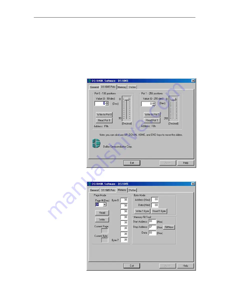
Figure 12 shows a typical “Pots” page (DS1845 in this case).  The pots page is probably where you will be
doing the majority of your evaluation.

The “Pots” page groups the controls for each pot.  Each pot can be modified in three ways:  with the edit
box, the spin control, or the slider control.  Secret: the pots can also be set/read using the memory page
discussed later.  The easiest way to move the pot is by using the edit box.  Simply click on the edit box,
type a decimal value in the appropriate range, and click on “Write to Pot”.  To read the pot setting, click on
“Read Pot”.  Another way to
move the pot is by using the
spin control (up/down arrows).
Click up or down until you
reach the desired value.  Then
click on “Write Pot”.  The most
fun method, however, is using
the slider control.  Drag the
slider the desired position and
release.  The value of the slider
will be sent to the pot when you
release the mouse button.  Also,
once a slider is selected, you can
use the keyboard to move it as
well.

For even more excitement,
enable the oscillator circuit (DIP
switch 5) and listen to the tone
change as you modify the pots.

Figure 12.  Typical “Pots” page.

Another common page is the
“Memory” page.  The Memory
page can be used to read and
write data to the EEPROM.  The
“Page Mode” allows you to
read/write memory one page at a
time (8 bytes).  The “Byte
Mode”, as its name suggests,
allows you to read/write one
byte at a time.  For fun, try
reading F8 and F9.  These are
the addresses of Pot 1 and Pot 0,
respectively.

Figure 13.  Memory page.

Summary of Contents for DS1840K

Page 1: ...inated with banana plugs bench supply or modified wall wart transformer for operation of the kit The DS1840K also provides an oscillator buzzer circuit that allows you to hear the potentiometers Kit C...

Page 2: ...buzzer depending on your jumper settings Figure 2 U1 Pin 1 Location 4 Connect the DS9123 serial port dongle to your PC 5 Now connect the cable 6 conductor from the DS9123 to the RJ 11 jack of the DS1...

Page 3: ...ers are installed on J4 or J5 Measuring from Hx x being 0 for pot 0 or 1 for pot 1 to Lx you will see the end to end resistance of the pot For a DS1845 010 you would measure 10KOhms Measuring from Wx...

Page 4: ...w you to hear the changes in resistance in case you do not have a multi meter handy This circuit is enabled disabled by DIP switch 5 labeled 555 ON To configure the circuit to work with the DS1845 set...

Page 5: ...rature range For more detailed information please refer to the datasheet The physical device pins associated with resistor 0 are L0 and H0 Resistor 1 has its own pins L1 and H1 Notice that since these...

Page 6: ...the Write Protect WP signal has an internal pull up resistor If the device is write protected then the wiper can not be moved and the memory can not be modified The defaultDIP switch settings for the...

Page 7: ...S9123 not found then click on the radio button next to COM2 Then click Apply If the status box displays DS9123 ready you are ready to continue Otherwise if you are still experiencing difficulties refe...

Page 8: ...lick on Write to Pot To read the pot setting click on Read Pot Another way to move the pot is by using the spin control up down arrows Click up or down until you reach the desired value Then click on...

Page 9: ...000 Figure 14 2 Wire page The DS1847 48 page allows you to display the current temperature as well as the corresponding resistor values from the lookup tables In addition a fill tool is provided to si...

Page 10: ...The DS1847 only has two memories these being the lookup table for Resistor 0 and the lookup table for Resistor 1 The DS1848 however has both lookup tables as well as a user EEPROM Figure 16 DS1847 48...

Page 11: ...Getting Started with the DS1840K 11 of 13 DS1840K Demo Board Schematic Figure 17 DS1840K Demo Board Schematic...

Page 12: ...with the DS1840K 12 of 13 Inside the DS9123 Serial Port Dongle Figure 18 DS9123 Schematic Check our FTP site for more DS9123 information to be added soon Contact information can be found at the end o...

Page 13: ...orld Wide Web Site www dalsemi com Ordering Information www dalsemi com products ordering pdf FTP Site ftp ftp dalsemi com pub system_extension pots Datasheets www dalsemi com datasheets pdfindex html...

Reviews: