Dallas Semiconductor DS1840K Instructions And Operating Download Page 7

                                                                                                               Getting Started with the DS1840K . . .

7 of 13

Using the DS1840K Software

Before starting the DS1840K Software, make sure that a device is properly installed and that power is
applied to the banana jacks.  Also, be certain that the serial port dongle (DS9123) and cable are connected.

To start the application, go the Start menu and select:

Start\Programs\Dallas Semiconductor\DS1840K Kit\DS1840K

Or, if you chose not to install, look for the executable named 

DS1840K.EXE

 and double click it.

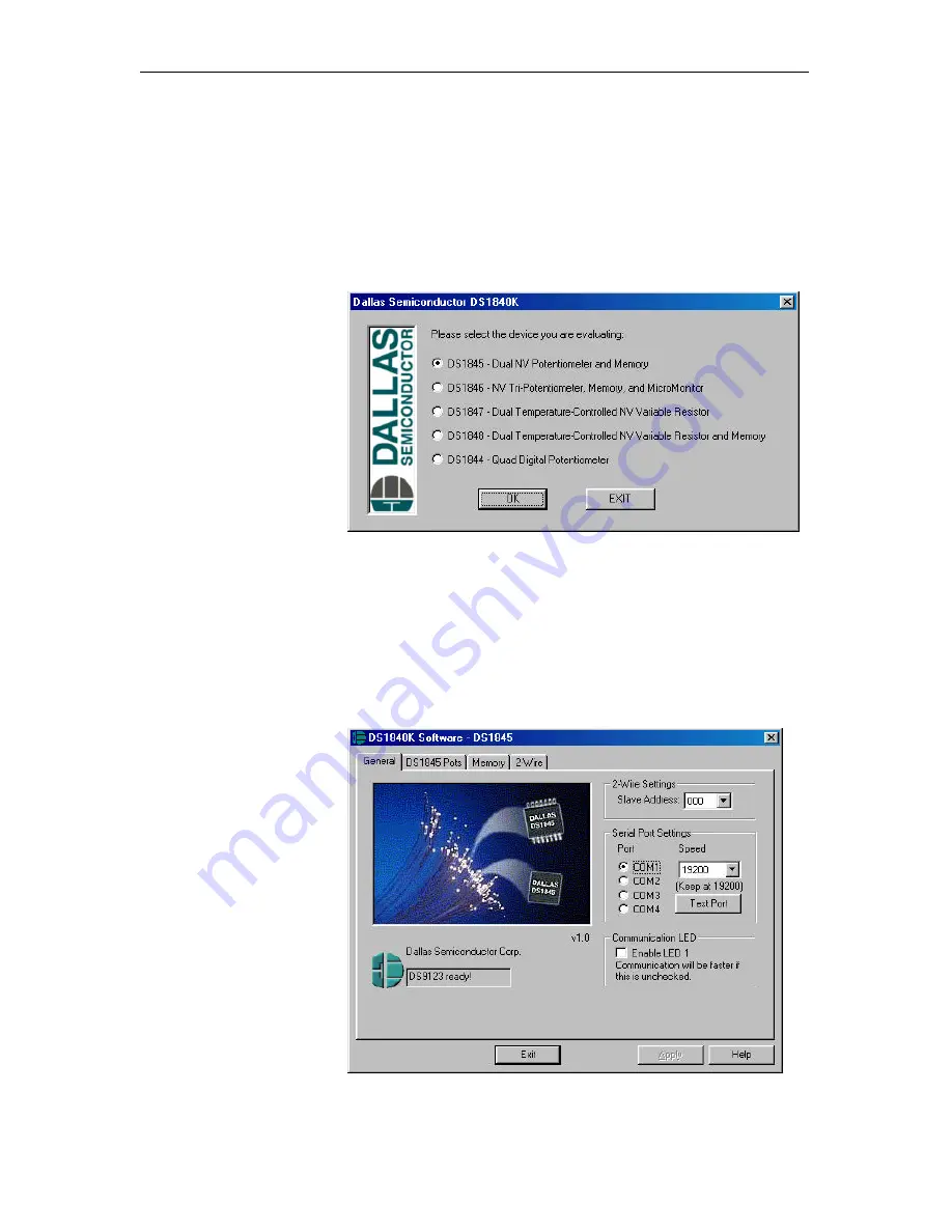
When the following dialog
box appears (Figure 10),
simply choose the device that
you would like to evaluate and
click “OK”.

Figure 10.  DS1840K device selection dialog box.

The DS1840K Kit Software finally appears.  The first item to look for is the status in the lower left corner.
If the DS9123 (connected to the serial port) is found, then the text should read “DS9123 ready!”.  LED2 on
the board should also be illuminated.  LED2, if lit, indicates that the serial port is now open.  If the status
box displays “DS9123 not found!”, then click on the radio button next to “COM2”.  Then click “Apply”.  If
the status box displays “DS9123 ready!”, you are ready to continue.   Otherwise, if you are still
experiencing difficulties, refer to the “Troubleshooting” section of this document.

The kit software is based on Windows property sheets.  The first “page” that appears is the General page
(see Figure 11).  This page is
common to all of the DS184X
devices.  In addition to the
status box already discussed,
the General page also contains
the “Serial Port Settings”
options.  If you ever need to
change the COM port, do not
forget to click on “Apply” so
the changes will take affect.
In the “Serial Port Settings”
box you will also find a Test
Port button.  This button is
only necessary for diagnosing
serial port and DS9123
problems.  The General page
also contains the selection for
the 2-Wire Slave Address.
This address needs to match
the DIP switches for A0, A1,
and A2.  The default of the 

Figure 11.  DS1840K General page.

Slave Address is 000, which matches the default DIP switch settings.  The last option found on the General
page is the Enable LED1 checkbox.  While LED2 indicates that the serial port is open, LED1, if checked,

Summary of Contents for DS1840K

Page 1: ...inated with banana plugs bench supply or modified wall wart transformer for operation of the kit The DS1840K also provides an oscillator buzzer circuit that allows you to hear the potentiometers Kit C...

Page 2: ...buzzer depending on your jumper settings Figure 2 U1 Pin 1 Location 4 Connect the DS9123 serial port dongle to your PC 5 Now connect the cable 6 conductor from the DS9123 to the RJ 11 jack of the DS1...

Page 3: ...ers are installed on J4 or J5 Measuring from Hx x being 0 for pot 0 or 1 for pot 1 to Lx you will see the end to end resistance of the pot For a DS1845 010 you would measure 10KOhms Measuring from Wx...

Page 4: ...w you to hear the changes in resistance in case you do not have a multi meter handy This circuit is enabled disabled by DIP switch 5 labeled 555 ON To configure the circuit to work with the DS1845 set...

Page 5: ...rature range For more detailed information please refer to the datasheet The physical device pins associated with resistor 0 are L0 and H0 Resistor 1 has its own pins L1 and H1 Notice that since these...

Page 6: ...the Write Protect WP signal has an internal pull up resistor If the device is write protected then the wiper can not be moved and the memory can not be modified The defaultDIP switch settings for the...

Page 7: ...S9123 not found then click on the radio button next to COM2 Then click Apply If the status box displays DS9123 ready you are ready to continue Otherwise if you are still experiencing difficulties refe...

Page 8: ...lick on Write to Pot To read the pot setting click on Read Pot Another way to move the pot is by using the spin control up down arrows Click up or down until you reach the desired value Then click on...

Page 9: ...000 Figure 14 2 Wire page The DS1847 48 page allows you to display the current temperature as well as the corresponding resistor values from the lookup tables In addition a fill tool is provided to si...

Page 10: ...The DS1847 only has two memories these being the lookup table for Resistor 0 and the lookup table for Resistor 1 The DS1848 however has both lookup tables as well as a user EEPROM Figure 16 DS1847 48...

Page 11: ...Getting Started with the DS1840K 11 of 13 DS1840K Demo Board Schematic Figure 17 DS1840K Demo Board Schematic...

Page 12: ...with the DS1840K 12 of 13 Inside the DS9123 Serial Port Dongle Figure 18 DS9123 Schematic Check our FTP site for more DS9123 information to be added soon Contact information can be found at the end o...

Page 13: ...orld Wide Web Site www dalsemi com Ordering Information www dalsemi com products ordering pdf FTP Site ftp ftp dalsemi com pub system_extension pots Datasheets www dalsemi com datasheets pdfindex html...

Reviews: