MINIMAX XL
Page 26
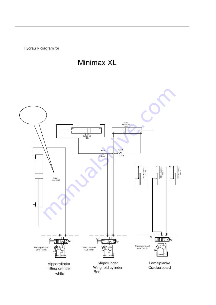
Hydraulic diagram
MINIMAX 630: 90/50-900 91838
Page 1: ...MINIMAX EN 630 and 830 cm Serial no 00100 XXXX ...
Page 2: ......
Page 3: ... number A spare parts list is included at the back of this manual EU DECLARATION OF CONFORMITY DALBO A S DK 7183 Randbøl declares herewith that the above machine is manufactured in accordance with the provisions of directive 2006 42 EC which replaced directive 98 37 CC and change directives 91 368 ECC 93 44 ECC and 93 68 ECC on harmonisation of member state legislation con cerning health and safet...
Page 4: ...g drawbar height 13 OPERATION 14 Extending and retracting 14 Extending 14 Retract 15 Weight equalisation 16 Operating speed 16 MAINTENANCE 17 Lubrication 17 Adjustment 18 Wheels 18 Hydraulics 18 REPLACEMENT AND REPAIRS 19 Hydraulics 19 Replacing extend cylinder for extending and retracting side sections 19 Replacing raise lower cylinder 21 Replacing gaskets on raise lower cylinder 22 Removal fitti...
Page 5: ...C DIAGRAM 26 ACCESSORIES 27 Greenline roller for grass 27 Frost safety 27 Levelling board 27 Board hydraulic system 28 Bleeding the system 28 Crackerboard 28 Seed drill 29 Filling seed 29 GUARANTEE 30 SCRAPPING 31 SPARE PARTS 32 ...
Page 6: ...hin the machine s extension radius before operating Operate machine only from inside the tractor When roller is folded together check the side sections are locked Check all control handles are secured against accidental operation Before leaving the tractor or making adjustments performing maintenance or repairs on the roller extend fully and lower to ground or maintain in transport position apply ...
Page 7: ...s spilt collect and deliver to a destruction point Clean hands thoroughly after contact with oil and grease Change oil stained clothing immediately Hydraulic oil can be harmful to the skin Hydraulic oil released under high pressure can penetrate the skin and cause severe injury In the event of injury seek medical help immediately Assembly Danger of crushing Ensure no personnel are between implemen...
Page 8: ...ance and repair instructions and that original spare parts are always used The roller may only be used maintained or repaired by personnel familiar with it and who are aware of the risks that can be involved The manufacturer cannot be held liable for injury or damage arising from modi fications made to the machine performed without prior permission from the manufacturer Neither can the manufacture...
Page 9: ...nto main sections Safety Description of the machine including settings Starting routine and running Accessories Maintenance Repairs The following symbols represent Points which are important to functionality and service life Points relevant to safety Delivery The roller is delivered complete on a trailer Always use a rig with straps attached to the mid section and ensure machine is balanced when l...
Page 10: ...ss Fields on which the machine is used must be in a good state of agricultural maintenance i e without major unevenness or potholes The machine can only be used when drawn by a tractor attached to the tractor towbar Max speed when in use is 10 km h Speed must always be adapted to suit the terrain Any other use of the machine which does not meet the above conditions will be considered as unauthoris...
Page 11: ...e sections in order to achieve uniform rolling across the full width of the machine The drawbar on the 830 version is extended to make room for the longer side sections when in transport position MINIMAX is designed to take rollers up to 61 cm in diameter but not 60 cm Crosskill rollers due to the construction of the rings which require more room in the frame than is available MINIMAX is designed ...
Page 12: ...ng and single acting hydraulic outlet where the double acting is used for extending and single acting for rais ing lowering Table 1 Hose markings Cylinder name Colour Outlet Function Raise lower cylin der White Single acting Raises the roller up onto its wheels and down into working position Fold weight equalisation Red Double acting Folds side sections up out and acts as weight equalisation from ...
Page 13: ...re maximum use To achieve uniform pressure applied on the ground the drawbar must be correctly set up for the tractor used Towbar height on tractor must be approx 45cm on the 630 and approx 55 cm on the 830 Adjusting drawbar height Fig 2 To achieve uniform pressure applied on the ground the draw bar must be correctly set up for the tractor used Fig 3 B Height under drawbar 45cm on 630 55cm on 830 ...
Page 14: ...the machine must always be performed with tractor parked and on a reasonably level surface Ensure there are no personnel within the machine s working radius when extending or retracting Extending Fig 4 1 Lift side sections from transport hook A using raise lower cylinder marked White Fig 5 2 Set extend cylinder marked Red to fully extend side sec tions 3 Activate raise lower cylinder to lower roll...
Page 15: ...lower cylinder to lower roller into transport hooks Fig 10 Always observe the correct sequence when retracting I e operate the side section extend cylinders to maximum extension first and then take them out of flow position Activate raise lower cylinder lift rollers from wheels If the ex tend cylinders are not taken out of flow position before the raise lower cylin der is activated the side sectio...
Page 16: ... sections in transport position Important The machine must always be fully retracted in transport position when setting up the weight equalisation system Operating speed An operating speed of 6 10 km h is recommended but always operate according to conditions Power requirement will depend on soil type terrain and speed But the most im portant factor is whether the machine is fitted with a crackerb...
Page 17: ...eck all split pins and bolts to avoid mechanical failure Check hydraulic system for leaks Lubrication Fig 9 Lubrication points Number of nipples Lubrication in tervals hours Balloon Flange bearings 6 50 A Rotation pin for extending side sections 2 25 D Extend cylinder 2 50 B Rotation pin for raise lower 2 50 C Wheel hub 2 50 E Lubricate all lubrication points at least once annually A B C D B E ...
Page 18: ... of a turn until hole aligns with axle Turn wheel check for resistance A little play should be detected in the hub housing when rocking wheel from side to side If play is excessive repeat process 4 Replace split pin 5 Fill hub cap full with grease Replace Hydraulics Check all hydraulic hoses for wear or cracks Check all hoses for crimping Lubricate exposed rams with oil or pressure resistant greas...
Page 19: ...ition key removed to prevent accidental start Particular attention must be paid to safety when repairing hydraulics Before commencing work depressurise hydraulic system and support part being worked on Always ensure hydraulic system is bled after repairs and before use to prevent mechanical breakdown and injury to person Hydraulics Replacing extend cylinder for extending and retracting side sectio...
Page 20: ...jury and personnel and damage to the ma chine Ensure no personnel are within the extension radius of the side sections Replacing gaskets REMOVAL 1 Drain oil from cylinder use compressed air to move ram backwards and forwards if required to force oil out 2 Extend ram to centre position Screw upper part pos 3 30 mm outwards If upper part is stuck heat front of sleeve to approx 300 C and allow to coo...
Page 21: ... oil for 12 hours after use of Loctite 5 Lubricate collar shoe pos 9 and cylinder tube end inside using lubricating oil Push ram into centre position 6 Screw on and tighten the upper part pos 3 Replacing raise lower cylinder Fig 18 Extend roller and relieve pressure on raise lower cylinder A 1 Disconnect hoses from cylinder 2 Support cylinder 3 Remove split pins in pins remove pins 4 Remove cylind...
Page 22: ...per part pos 5 6 7 8 9 along with collar shoe 7 Clean all parts and check for particles etc Check for rust around scraper ring pos 5 on upper part If detected remove thoroughly Assembly 1 Fit new gaskets pos 5 6 7 8 9 in upper part plus collar shoe 2 Apply oil to thread in upper part pos 3 and cylinder tube pos 1 3 Fit upper part pos 3 on ram shaft 4 Fit collar shoe pos 4 and screw on lock nut sec...
Page 23: ...emove wheel Replace wheel hand tighten wheel nuts Lower wheels to ground Tighten wheel nuts to 300 Nm Ensure wheel nuts and wheel surfaces are clean to avoid nuts loosening Replacing wheel bearings Fig 22 1 Remove hub cap pos 21 2 Remove split pin pos 20 3 Remove castle nut pos 19 4 The axle pos 2 can now be tapped out 5 Remove bearings pos 17 18 6 Remove seal ring pos 16 ...
Page 24: ...ly extended with the rings resting on the ground A crane is recom mended for removal and replacement procedures Replacing side section rollers If no crane is available remove both side section axles to prevent roller tipping over Fig 23 1 Slacken bolts A 2 Attach lifting gear to box sec tion arm on side section Tighten straps until bolts A are loose and can be removed 3 Activate raise lower cylind...
Page 25: ...ng middle roller Fig 24 1 Use lifting points A on both sides 2 Slacken bolts B 3 Lift using crane until bolts are loose 4 Remove bolts 5 Lift using crane until rings can be rolled out 6 Reverse procedure for assem bly Do not activate hydraulics if there are personnel within machine extension radius A B ...
Page 26: ...MINIMAX XL Page 26 Hydraulic diagram MINIMAX 630 90 50 900 91838 ...
Page 27: ...gain Adjustment is correct when the scraper is as close as possible to the roller without touching the roller surface at any point during rotation Frost safety If the machine is exposed to frost it is very important that the rollers are drained Failure to do so can mean a risk of the rollers deforming or splitting Fill drain the rollers via the plugs F Levelling board Machines with Greenline rolle...
Page 28: ... depth using the hydraulics the cylin ders must be as short as possible Maintain pressure in the system in this posi tion for a while try to make the cylinders even shorter even if the cylinders are fully retracted The cylinders are designed to allow oil to pass the ram via a channel even when at maximum retraction This forces any air out of the system Crackerboard MINIMAX can be fitted with a hyd...
Page 29: ...speed or pneumatic box a jockey wheel runs on the ground or the centre roller to ensure the correct amount of seed regardless of the tractor speed variants P Box Speed seed box mounted on a MINIMAX 630 in operational setting Filling seed The machine must be fully extended before filling the seed box When fully extend ed the seed box is at a height above the ground which makes filling easy and safe...
Page 30: ...ns without the written consent of Dalbo A S Non original spare parts used Dalbo A S cannot be held liable for consequential damage loss of earnings or profit or as a result of de fects Dalbo A S cannot be held liable for labour costs other than those reasonably incurred for repairs or the replacement of parts covered by the guarantee Dalbo A S cannot be held liable for the following costs Setting ...
Page 31: ...f the weight of any given part when removing or disassembling All parts must be supported or lifted to avoid danger of falling Disconnect hydraulic hoses and cylinders and drain oil Collect oil in container to avoid pollution Send oil and hoses for destruction All iron used in the machine can be recycled ...
Page 32: ...MINIMAX XL Page 32 Spare parts ...