background image

 CENTER THREADED RODS

ON YOKE WITH ENOUGH GAP

BETWEEN TO GO AROUND POLE

REV:

01

DATE:

10 DEC 19

DESCRIPTION:

PER CN-91941, UPDATED HARDWARE SIZE FOR SPEAKER

BY:

DRO

4920

THE CONCEPTS EXPRESSED AND DETAILS SHOWN ON THIS DRAWING

ARE CONFIDENTIAL AND PROPRIETARY. DO NOT REPRODUCE BY

ANY MEANS WITHOUT THE EXPRESS WRITTEN CONSENT OF

DAKTRONICS, INC. OR ITS WHOLLY OWNED SUBSIDIARIES.

COPYRIGHT 2019 DAKTRONICS, INC. (USA)

THIRD ANGLE PROJECTION

PROJECT:

SPORTSOUND SYSTEMS

TITLE:

POLE MOUNTING; 15.5"DIAMETER AND UNDER; SPK-CX

DATE:

04-NOV-19

DIM UNITS:

INCHES [MILLIMETERS]

SHEET

REV

SCALE:

1/10

DO NOT SCALE DRAWING

1 OF 1

01

DESIGN:

DOPPELT

JOB NO.

FUNC - TYPE - SIZE

4306807

DRAWN:

DOPPELT

P1870

F - 10 - B

***CRITICAL***

DO NOT USE ANY LUBRICANT

ON ANY MOUNTING HARDWARE

OR WARRANTY WILL BE VOIDED

STEP 1

ATTACH THREADED ROD TO YOKE AS SHOWN

STEP 2

POLE MOUNT YOKE TO POLE AS SHOWN

POINT YOKE WHERE AUDIO NEEDS TO GO

STEP 3

MOUNT SPEAKER TO YOKE

NOTES:

 - BOLT TORQUE:  30 FT-LB

 - THREADED RODS RUN ALONG BOTH SIDES OF POLE

 - NO DRILLING NECESSARY


REFERENCE DWG-4561929 FOR 

DETAILS ON AIMING SPEAKER

1/2" NUT

1/2" NUT

1/2" FLAT WASHER,

LOCK WASHER, AND NUT

TIGHTEN THESE TOGETHER

TOP VIEW

STEP 1

ROTATED VIEW

STEP 1

THREADED HOLES ON

RIGHT SIDE WHEN FACING 

SPEAKER FRONT

1/2" THREADED ROD

VERTICAL POLE

REAR MOUNTING ANGLE

SPEAKER YOKE

1/2" FLAT WASHER

LOCK WASHER, AND NUT

**TIGHTEN THESE

REAR BOLTS 1ST**

TOP VIEW

STEP 2

1/2" NUT

TIGHTEN THESE

INNER NUTS LAST

AUDIO

DIRECTION

THREADED HOLES ON

RIGHT SIDE WHEN FACING 

SPEAKER FRONT

ROTATED VIEW

STEP 2

SIDE VIEW

STEP 3

3/8" FLAT WASHER,

LOCK WASHER, AND BOLT

USE DAKTRONICS LABEL

TO AIM SPEAKER

#8-32 SCREW

ROTATED VIEW

STEP 3

THREADED HOLES ON

RIGHT SIDE WHEN FACING 

SPEAKER FRONT

PPaarrtt  ##  --  00AA--11775566--00007799

VVeerrssiioonn  --  0011..55

D

Deessccrriippttiioonn  --  PPO

OLLEE  M

MTTG

G;;  SSPPKK--C

CXX--11000011,,  U

UPP  TTO

O  1155..55""  D

DIIAAM

MEETTEER

R

LLiiffeeccyyccllee  SSttaattee  --  FFuullll  PPrroodduuccttiioonn

LLaasstt  M

Mooddiiffiieedd  BByy  --  ddooppppeelltt

LLaasstt  M

Mooddiiffiieedd  --  22001199--1122--1188

Summary of Contents for Sportsound SS-200

Page 1: ...201 Daktronics Drive Brookings SD 57006 5128 www daktronics com support 800 325 8766 SPORTSOUND SS 200 AUDIO SYSTEM INSTALLATION MANUAL P1756 DD4310070 Rev 00 11 March 2020...

Page 2: ...art of this book covered by the copyrights hereon may be reproduced or copied in any form or by any means graphic electronic or mechanical including photocopying taping or information storage and retr...

Page 3: ...he Control Enclosure 7 4 Electrical Installation 8 Portable System 8 Power IN 8 Signal IN 8 Speaker OUT 8 Permanent System 9 Power IN 9 Signal IN 9 Speaker OUT 9 Grounding 9 5 Troubleshooting 10 Ampli...

Page 4: ...This page intentionally left blank...

Page 5: ...ipment or allow it to get wet Always turn off and or unplug the control equipment when it is not in use This keeps equipment protected from power spikes and lightning Inspect equipment for shipping da...

Page 6: ...ct a Daktronics sales coordinator or project manager Daktronics Nomenclature Most components have a white label that lists the part number Figure 2 Part numbers will also appear on certain drawings If...

Page 7: ...ety approval Loudspeaker The SPK CX 1001 loudspeaker Figure 3 is made from a durable weatherproof black ABS copolymer with a fine texture finish The speaker grille is made from powder coated perforate...

Page 8: ...trol racks Refer to the manual provided with the control rack for proper operation Note The SS 200 will typically be controlled by the SSR AM mixer For more information refer to the Sportsound SSR AM...

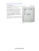
Page 9: ...ing this mounting yoke a speaker can be installed on a pole wall or roof Note Speakers should never be installed facing upward This will void the warranty Pole Mounting Reference Drawings Pole Mountin...

Page 10: ...ud joist or other structural member rather than only to drywall or other non structural material Ensure adequate clearance to rotate and tilt the speaker to the desired angle Ensure that any holes dri...

Page 11: ...mounts in a closet adjacent to the sound system or directly on the wall using 1 4 hardware The head of the hardware must not be larger than 5 8 or it will not fit through the keyholes on the rear of...

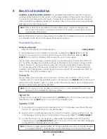
Page 12: ...mounted within range of the 30 9 1 m speaker whip This provides a maximum of 310 94 5 m from the speaker s to amplifier rack The Speaker Junction Box is to be mounted in an accessible location for th...

Page 13: ...the signal input plate Speaker OUT 1 Connected to the rear of each speaker is a 30 9 1 m speaker wire Route this wire to a local 1 gang junction box one per speaker 2 Route 1 pair 12 AWG speaker wire...

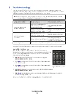
Page 14: ...Signal cable connection issue Check signal path from speaker to J box es to amplifier rack to control rack No full range audio One or more outputs muted Ensure no outputs are muted For more troublesho...

Page 15: ...box EC 1166 Cover w Gasket EC 1081 Strain Relief EC 1176 Wire Connector E 1184 Speaker Junction Box EC 4276769 Speaker Cable 1 pair 12AWG W 1745 Control Enclosure Description Part Number Amplifier QSC...

Page 16: ...m follow these steps 1 Call Daktronics Customer Service Market Description Customer Service Number Schools including community junior colleges religious organizations municipal clubs and community cen...

Page 17: ...t damage during shipment Electronic components such as printed circuit boards should be placed in an antistatic bag before boxing Daktronics does not recommend using packing peanuts when shipping 4 En...

Page 18: ...This page intentionally left blank...

Page 19: ...l drawings Reference Drawings Shop Drawing Standard Indoor Sound Amp Rack Mounting DWG 1152507 Schematic SS200 System Schematic DWG 4275565 Riser SS 200 Electrical Portable System DWG 4306293 Riser SS...

Page 20: ...This page intentionally left blank...

Page 21: ...MP RACK MOUNTING JROBERS 23 JUL 13 P1756 R 10 B 1 8 JROBERS 1152507 00 SPORTSOUND INDOOR AUDIO SYSTEM AMP RACK MOUNTING APPROVED APPROVED AS NOTED APPROVED AS NOTED RESUBMIT COMPANY SIGNED TITLE DATE...

Page 22: ...LF RED W 1109 BLU W 1078 BLK W 1081 RED W 1078 BLK BLK RED LOCAL JUNCTION BOX 0A 1756 0081 LJB 4 LF CONNECTIONS HF CONNECTIONS 14 SPEAKER REAR VIEW OPTIONAL OPTIONAL OPTIONAL 14 SPEAKER A 4287636 SPK...

Page 23: ...G FROM NL8 TO TB1 TB8 BY SPEAKER JUNCTION BOX MFG 6 USE SUPPLIED NL8 TO NL8 W 4303368 SPEAKON CABLE FOR CONNECTING PORTABLE AMPLIFIER RACK TO SPEAKER JUNCTION BOX W 1745 DETAILS 1 PAIR 12 AWG SPEAKER...

Page 24: ...ALL FOUR SPEAKER OUTPUTS SSR AM IS SHOWN ON THIS DRAWING BUT ANY SSR CONTROL SYSTEM CAN BE USED WITH SS200 SYSTEM W 1745 DETAILS 1 PAIR 12 AWG SPEAKER CABLE OUTER DIAMETER 0 352 COLOR BLACK RATED FOR...

Page 25: ...ALONG BOTH SIDES OF POLE NO DRILLING NECESSARY REFERENCE DWG 4561929 FOR DETAILS ON AIMING SPEAKER 1 2 NUT 1 2 NUT 1 2 FLAT WASHER LOCK WASHER AND NUT TIGHTEN THESE TOGETHER TOP VIEW STEP 1 ROTATED V...

Page 26: ...2 LONG 2 MINIMUM THREAD PENETRATION INTO WOOD MEMBERS LAGS MUST PENETRATE INTO WOOD STUDS STEEL STUD WALL ITW Bildex 1 4 14X3 TEK 3 SELF DRILLING SCREW FOLLOW ESR 1976 AND MANUFACTURER RECOMMENDATIONS...

Page 27: ...ALL HARDWARE CONNECTIONS USED FOR SPEAKER MOUNTING ROTATED VIEW YOKE ARROWS ARE DIRECTION OF AUDIO TARGET CENTER OF AUDIO TARGET SHOULD BE PERPENDICULAR TO CENTERLINE OF IMAGINARY LINE BETWEEN HOLES T...

Page 28: ...This page intentionally left blank...

Page 29: ...ite or perform a web search for the component model number When viewing a digital copy of this manual from www daktronics com manuals click on the appropriate manufacturer link below to view a compone...

Page 30: ...This page intentionally left blank...

Page 31: ...Daktronics Warranty Limitation of Liability 27 C Daktronics Warranty Limitation of Liability This section includes the Daktronics Warranty Limitation of Liability statement SL 02374...

Page 32: ...This page intentionally left blank...

Page 33: ...y per Incoterms 2020 otherwise End User shall pay transportation charges to return the Equipment back to the End User and such Equipment shall be shipped Ex Works Daktronics designated facility per In...

Page 34: ...Daktronics or M paint or refinishing the Equipment or furnishing material for this purpose 3 Limitation of Liability A Daktronics shall be under no obligation to furnish continued service under this W...

Page 35: ...ation of this warranty Alternatively an Extended Service Agreement may be purchased in conjunction with this Warranty for extended additional services For further information contact Daktronics Custom...

Page 36: ...This page intentionally left blank...

Reviews: