Electrical Installation
8
4 Electrical Installation
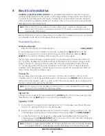
CAUTION – RISK OF ELECTRIC SHOCK:
Only qualified individuals should perform power
routing and termination to the system. It is the responsibility of the electrical contractors
to ensure that all electrical work meets or exceeds local and national codes. Failure to
follow installation guidelines will result in audible noise on the sound system and possible
damage to internal components.
Note:
This product is not provided with mains disconnect. Customer shall provide
disconnect at base of sound system location that meets or exceeds local and
national electrical codes.
Electrical installation will vary depending on whether the amplifier is housed in a portable
or permanent rack. Refer to the appropriate section below.
Portable System
Reference Drawings:
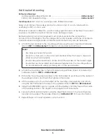
Riser; SS-200, Electrical, Portable System ........................................................
DWG-4306293
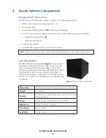
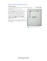
In a portable system, the amplifier is housed in a rolling rack (
) that can be
brought to the venue for an event and removed once it is finished. Refer to
DWG-
4306293
for a typical portable system setup with up to four speakers.
The portable system requires a permanently-mounted Speaker Junction Box within 30'
(9.1 m) of the amplifier rack location and up to 250' (76.2 m) from local 1-gang junction
box(es). The local 1-gang junction box(es) are to be mounted within range of the 30'
(9.1 m) speaker whip. This provides a maximum of 310' (94.5 m) from the speaker(s) to
amplifier rack. The Speaker Junction Box is to be mounted in an accessible location for
the portable amp rack to easily plug in.
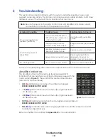
Power IN
The portable system requires one (1) 20 amp, 120 VAC circuit within 3' (0.9 m) of the
amplifier rack. Connect the included power cord between the
POWER
inlet on the rear of
the rack and the nearby outlet. A duplex outlet is recommended to also provide power
for the control rack (typically the SSR-AM).
Note:
Do not power on the amplifier rack if the front cover is installed! This will cause
damage to the amplifier by blocking airflow.
Signal IN
Connect the included XLR cable between the
OUTPUT
jack of the control rack (typically
the SSR-AM) and an
INPUT
jack on the rear of the amplifier rack.
Speaker OUT
1�
Connected to the rear of each speaker is a 30' (9.1 m) speaker wire. Route this wire
to a local 1-gang junction box, one per speaker.
2�
Route 1-pair, 12 AWG speaker wire in conduit from each 1-gang junction box to the
main Speaker Junction Box and terminate per the wiring diagram in
DWG-4306293
.
3�
Locate the 30' (9.1 m), 8-conductor cable inside the amplifier rack. Connect this
cable between the
SPEAKER OUTPUT
jack on the rear of the rack and the mating jack
on the bottom of the Speaker Junction Box.
Note:
If there is a single speaker within 30' of the portable amp rack, it may be possible
to connect directly to the Speaker Junction Box using no local junction boxes.

