


THE CONCEPTS EXPRESSED AND DETAILS SHOWN ON THIS DRAWING
ARE CONFIDENTIAL AND PROPRIETARY. DO NOT REPRODUCE BY
ANY MEANS WITHOUT THE EXPRESS WRITTEN CONSENT OF
DAKTRONICS, INC. OR ITS WHOLLY OWNED SUBSIDIARIES.
COPYRIGHT 2016 DAKTRONICS, INC. (USA)
THIRD ANGLE PROJECTION
BH
REV
TITLE:
PROJECT:
INCHES [MILLIMETERS]
DESIGN:
SCALE:
DIM UNITS:
DATE:
SHEET
DO NOT SCALE DRAWING
FUNC - TYPE - SIZE
DRAWN:
-
JOB NO.
-
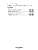
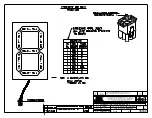
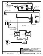
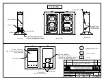
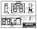
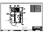
SCHEMATIC; BATTERY OPERATED TI-XXXX WITH HORN
KSEIDL
12 APR 15
P1753
E 03 B
NONE
SCOLGROVE
3333212
04
115V
0V
5
2
4
115V
16V
10
8
12V
0V
1
0V
6
0A-1192-5517
BATTERY
CHARGER
BLK
INTERFACE
BOARD
0P-1192-0097
BT1
BT-1023
12V 28AH
BATTERY
+
-
LED DRIVER
SEE PACKET FOR ASSY
NUMBER
S1
DRVR POWER
S-1125
J7
J1
J4
J6
J2
J3
P17
J17
J18
+
-
BLK
RED
RED
BLK
RED
BLK
RED
BLK
WHT
P7
P1
P4
P6
P3
BT2
BT-1023
12V 28AH
BATTERY
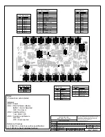
NOTE:
ALL CONDUCTORS ARE 18 AWG EXCEPT * INDICATES 22
AWG CONDUCTORS AND THE INLINE FUSES, F4, F5 AND F6
WHICH ARE 14AWG.
BATTERY TERMINALS MAY BE LOCATED ON DIFFERENT
SIDES OF THE BATTERY DEPENDING ON MANUFACTURER
OR HOW THE BATTERY IS INSTALLED. VERIFY THE
POLARITY ON THE BATTERY BEFORE CONNECTING THE
HARNESS.
F1, F2, AND F3 ARE PROVIDED WITH THE BATTERY
CHARGER, 0A-1192-5517.
F4 AND F5 ARE INLINE FUSE WITH 14 AWG WIRES. USE
WITH F-1031 (7 AMP, MDL) FUSE.
F6 IS AN INLINE FUSE WITH 14 AWG WIRES. USE WITH
F-1077 (1 AMP, MDL) FUSE.
F3
F1
F4
F5
RED
RED
J-1458
E-1044
BUTT CONNECTOR
RED
BLK
GRY
WHT
BLK
RED
BLK
BLK
WHT
1
2
WHT
TO
OUTLET
COVER SCREW
F6
1
2
3
4
1
2
3
4
J31 SIG IN
RED
BLK
BLK
1
2
3
9
1
2
3
4
5
6
7
8
9
4
5
6
7
8
WHT
GRY
BLK
1
2
1
2
1
2
1
2
1
2
BLK
BLK
1
4
2
3
1 2 3 4 5 6 7 8 9 10 1112
1 2 3 4 5 6 7 8 9 10 1112
1 2 3 4 5 6 7 8 9 10 1112
1 2 3 4 5 6 7 8 9 10 1112
WHT
WHT
TB-3
GRN
GRN
BLK
BLK
BLK
BLK
TB-2
TB-4
TB-1
GRN
GRN
J41
POWER INLET
T-1066
4-07-8016 CSA
J5
1
9
2
3
4
5
6
7
8
WHT
+
-
RED
BLK
1
2
3
4
1
2
3
4
P2
J2
A2
HORN CARD
0P-1192-0398
1
2
1
2
1
2
1
2
J3 P3
J1 P1
RED
BLK
P2
1
2
P18
1
4
2
3
P5
1
9
2
3
4
5
6
7
8
GRY
BLK
GRY
BLK
1
2
3
4
P2
GRY
BLK
GRY
BLK
OR
RED
BLK
RED
BLK
T1
OPTIONAL: HORN HARNESS FOR
GAME HORN FUNCTION.
TYPICALLY NOT NEEDED, FIELD
WIRED IF NEEDED.
STANDARD: ALWAYS
CONNECTED IN
MANUFACTURING.
HORN OPTIONAL
ON SOME
REV
DATE:
BY:
01
21 JUL 16
MTR
PER EC-22055, ADDED NOTE "HORN OPTIONAL ON SOME"
ABOVE HORN CARD DETAIL
F2
REV
DATE:
BY:
02
24 FEB 17
JSF
ADDED FUSE TO THE BLACK LEAD ON BT1.
BATTERY CHARGER
ADDED IN FINAL
ASSEMBLY
REV
DATE:
BY:
03
13 SEPT 17
CMS
PER EC-42166: REPLACED POWER JACK WITH J-1458
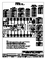
IF EXTERIOR HORN WILL BE
USED, ACCESS AND
DISCONNECT LUGS FROM
HORN AND ROUTE HORN
HARNESS THROUGH
PROVIDED CABLE ACCESS
HOLE ON SIDE OF TIMER
RECONNECT LUGS TO HORN
ASSEMBLY
USE 0A-1192-0469
HARNESS FOR
LACROSSE
IF 0A-1192-0471, 12VDC EXTERIOR
HORN IS INSTALLED, REMOVE
EXITING CONNECTOR AND
REPLACE WITH E-1184
E-1184
IF 0A-1192-0471, 12VDC EXTERIOR HORN IS USED,
UNPLUG CURRENT CABLE HARNESS AND ROUTE OVER
TO THE P6 HARNESS FROM THE BATTERY. REMOVE
CURRENT SPLICE ON POSITIVE TERMINAL AND
COUPLE TOGETHER WITH RED WIRE FROM TWO PIN
CABLE USING E-1184. CUT CURRENT NEGATIVE LEAD
AND COUPLE BACK TOGETHER WITH TWO PIN
HARNESS BLACK LEAD USING AN E-1184 CONNECTOR.
REV
DATE:
BY:
04
10 NOV 20
MTR
PER CN-112028, ADDED DETAILS FOR 0A-1192-0471 PACKET
PPaarrtt ## -- D
DW
WG
G--0033333333221122
VVeerrssiioonn -- 0044..22
D
Deessccrriippttiioonn -- N
N BB SSC
CH
HEEM
MAATTIIC
C;; BBAATTTTEER
RYY O
OPPEER
RAATTEED
D TTII--XXXXXXXX W
WIITTH
H H
HO
OR
RN
N
LLiiffeeccyyccllee SSttaattee -- FFuullll PPrroodduuccttiioonn
LLaasstt M
Mooddiiffiieedd BByy -- m
mrruuffeerr
LLaasstt M
Mooddiiffiieedd -- 22002200--1111--1100
Summary of Contents for P1753
Page 4: ...This page intentionally left blank...
Page 26: ...This page intentionally left blank...
Page 28: ......
Page 38: ...This page intentionally left blank...