


Troubleshooting
12
6
Troubleshooting
Disconnect power before doing any repair or maintenance work on the display. Permit
only qualified service personnel to access internal display electronics. Disconnect power
when not using the display.
Troubleshooting Table
The table below lists potential problems with the display and indicates possible
causes and corrective actions. This list does not include every symptom that may be
encountered, but it does present several of the most common situations that may occur.
Problem
Possible Cause
Solution/Items to Check
Display doesn’t light, and
console doesn’t work
No power to the display
Flip power switch
ON
(up).
Check that the display has 120 VAC power.
There may be a problem with the
batteries/charger. Refer to the
.
No power to console
Ensure the console is plugged into a 120
VAC power supply.
Exchange the console with a working one,
and enter the correct sport code and/or
radio settings to test. Replace if necessary.
Display digits do not
light, but console works
No wired signal from
control console
Check that the display is receiving 120 VAC
or battery power.
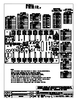
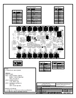
Verify the red
DS5
(or
DS2
) LED on the driver
lights up when sending commands from
the control console. See
.
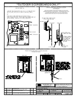
No radio signal from
control console
Check the receiver (display) and
transmitter (console) radio settings.
Check that the green
POWER
and amber
RADIO IN RANGE
indicators on the radio
receiver in the display light up when the
control console is powered on. Keep the
console 20–1500' (6–457 m) away.
Move the console 20–30' (6–9 m) from the
display and test again. Verify that both the
console and display antennas are securely
tightened and in a vertical position.
Replace the radio receiver.
No signal to driver
Check that the display is receiving 120 VAC
or battery power.
Verify the red
DS5
(or
DS2
) LED on the driver
lights up when sending commands from
the control console. See
.
Exchange driver with a working one of the
same part # to verify the problem. Replace
.
No power to driver
Verify the red
DS8
(or green
DS1
) LED on
the driver is always lit up when the display is
powered on. See
.
Summary of Contents for P1753
Page 4: ...This page intentionally left blank...
Page 26: ...This page intentionally left blank...
Page 28: ......
Page 38: ...This page intentionally left blank...