NPN-410X Series Border Installation Quick Guide
Page 1 of 1
DD3838321
Rev 02
12 July 2019
201 Daktronics Drive
Brookings, SD 57006-5128
www.daktronics.com/support
800.325.8766
Flat Border
Tools
Part
Part Description
Cordless screw gun
Attaches borders to section
Flat-head bit or screwdriver
Removes top alignment pins
T-25 TORX
®
bit (Daktronics part number
TH-1118)
Attaches borders
Identify Part
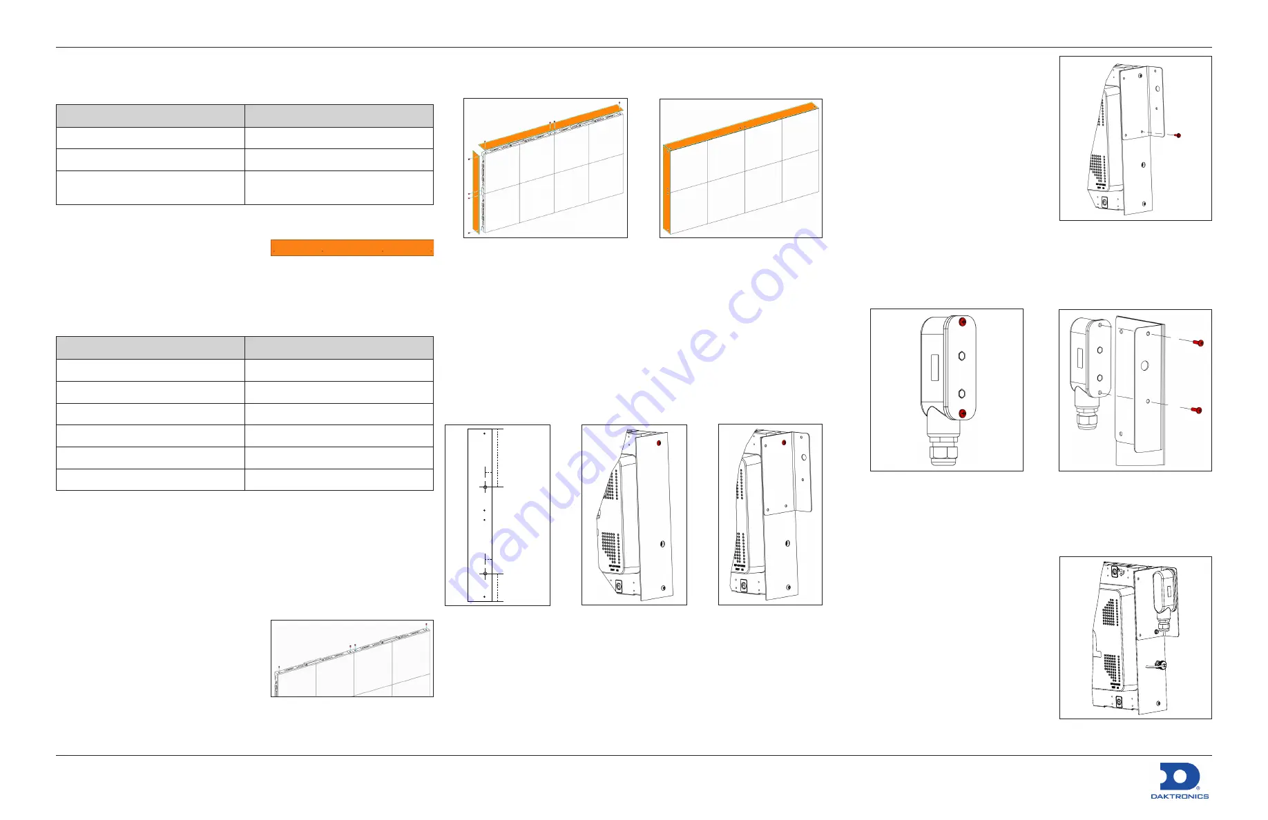
There are six different border sizes for
the NPN-410X display series: one-, two-,
three-, and four-module-high borders
and two- and four-module-wide
borders. The part numbers are etched into the metal on each border for
identification purposes. Refer to the table below for part numbers and to
Figure 1
for a visual.
Part Number
Part Description
0M-3807592
Flat Border, Side, 1-High
0M-3807594
Flat Border, Side, 2-High
0M-3807596
Flat Border, Side, 3-High
0M-3807598
Flat Border, Side, 4-High
0M-3807600
Flat Border, Top/Bottom, 2-Long
0M-3807602
Flat Border, Top/Bottom, 4-Long
Install Border
Borders are attached either before the display is mounted to the structure
or after if site conditions allow for tool clearance around the mounted
display. If the borders must be installed before the sections, only
one-module-high (Daktronics part number 0M-3807592) and
two-module-wide (0M-3807600) borders are available. Borders longer than
one module high or two modules wide must be installed after the display
sections are mounted to the structure.
1.
Remove the top alignment pins
from the top row of panels. Refer to
Figure 2
.
2.
Select the correct border size
according to the Shop Drawing.
3.
Use a clean rag to wipe off the
perimeter of the panel receiving the
border.
Figure 1:
Flat Border
Part number
Figure 2:
Prepare Top Row of Panels
4.
Bring the border into position. The holes should be oriented toward the
front of the display to align with the threaded holes in the panels. Refer
to
Figure 3
.
Figure 3:
Install Flat Border
Figure 4:
Attached Flat Border
5.
Use a
1
/
4
" T-25 TORX
®
bit (TH-1118) to remove the M5-0.8 x 10 mm
machine screws (HC-3809581) to fasten the border to the panel
perimeter in all pre-punched hole locations on the border. Each panel
has threaded holes for borders on all four sides. Refer to
Figure 4
for the
finished appearance.
Light Sensor
Install Mounting Bracket
Border modifications are required for light sensors. Drill a 0.5" diameter hole
1" from the front of the border and either 9.132" from the top of the border
or 4.375" from the bottom. Refer to
Figure 5
and
DWG-3898915
for details.
Figure 5:
Modify Border
for Light Sensor
Front of
border
1"
9.132"
4.375"
1"
Figure 6:
Remove
Machine Screw
Figure 7:
Position
Mounting Bracket
1.
Use a
1
/
4
" T-25 hex bit (TH-1118) to remove the M5-0.8 x 10 mm machine
screw (Daktronics part number HC-3809581) above the panel mount
location and set the screw aside for
Step 2
. Refer to
Figure 6
.
2.
Position the mounting bracket on the border, aligning the top-right
hole of the bracket with the hole on the border where the screw was
removed in
Step 1
. Use a
1
/
4
" T-25 hex bit (TH-1118) to secure the
M5-0.8 x 10 mm machine screw (HC-3809581) from
Step 1
into the hole.
Refer to
Figure 7
.
3.
Use a
5
/
16
" socket/driver to install a
#10-16 x 0.75 TEK screw (HC-1530)
through the bottom-right hole in the
bracket. Refer to
Figure 8
.
Install Light Sensor
Refer to
DWG-3898915
,
DWG-3887723
, and
the steps below for installation details.
1.
Ensure the display is physically mounted
with power and signal installed.
2.
Ensure power is disconnected from the
display.
3.
Mount the light sensor in a suitable
location.
a.
Use a Phillips screwdriver to remove the two #8-32 x 0.500 machine
screws (HC-1144) in the light sensor and set the screws aside for
Step 3.b
. Refer to
Figure 9
.
Figure 9:
Remove Light Sensor
Screws
Figure 10:
Position Light Sensor on
Mounting Bracket
b.
Position the light sensor on the flange of the mounting bracket and
secure the sensor in place with the two screws from
Step 3.a
. Refer
to
Figure 10
.
4.
Locate the PLR closest to the light
sensor mounting location and connect
the light sensor. Only one light sensor
can be connected to each PLR.
a.
Connect the four-pin plug
(W-3884831) to the PLR.
b.
Mount the panel mount M12 jack
(W-3884831) per
DWG-3898915
.
Wrap and secure the excess cable.
5.
Connect the light sensor harness
(W-2532) to the panel mount M12 jack
installed in
Step 4
. Refer to
Figure 11
.
6.
Secure the cables as needed.
Figure 8:
Install TEK Screw
Figure 11:
Connect Light Sensor
to Panel Mount Jack
Summary of Contents for NPN-4100 Series
Page 4: ...This page intentionally left blank...
Page 8: ...This page intentionally left blank...
Page 10: ...This page intentionally left blank...
Page 14: ...This page intentionally left blank...
Page 16: ...This page intentionally left blank...
Page 18: ......
Page 20: ......
Page 28: ......
Page 30: ...This page intentionally left blank...


