background image

Replacing Parts

22

10  Replacing Parts

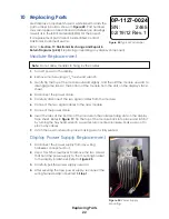
Most display components have a white label that lists the 

part number in bold as shown in 

Figure 24

. Part numbers 

may also appear on illustrations and reference drawings 

as well as in the Bill of Materials (BOM) for the project. 

If a replacement part cannot be identified, contact 

Daktronics Customer Service.
Refer to 

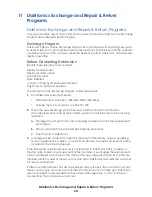
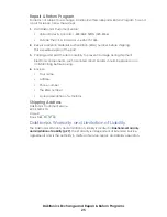
Section 11: Daktronics Exchange and Repair & 

Return Programs (p�24)

 if replacing or repairing any display component.

Module Replacement

Note: 

Do not allow modules to hang by the cables.

1� 

Turn off power to the display.

2� 

Remove module using a 

1

/

8

" hex head wrench.

3� 

Gently tip the top of the module outward slightly, and then lift the module upward to 

disengage the tabs at the bottom of the module from the slots on the display’s face 

sheet.

4� 

Disconnect the power cable.

5� 

Carefully disconnect the two signal cables from the module.

6� 

Connect the two signal cables to the new module.

7� 

Connect the power cable.

8� 

Insert the tabs at the bottom of the module in the corresponding slots on the display 

face sheet. Refer to 

Figure 17

. Tip the top of the module back into place and latch it 

by turning the hex head wrench a quarter-turn counter-clockwise. Make sure not to 

pinch any cables.

9� 

Latch the new module into place making sure it is fully seated.

Display Power Supply Replacement

1� 

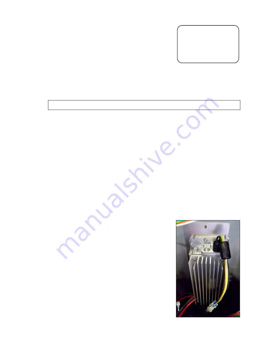
Disconnect the power supply from any wiring 

harnesses connected to it.

2� 

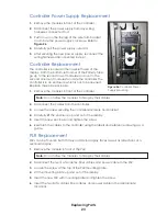
Use a Torx T25 screwdriver to remove the two screws 

that hold the power supply to the mounting bracket 

to the display backsheet. Refer to 

Figure 25

.

3� 

Carefully pull the power supply outward.

4� 

After securing the new power supply, reconnect the 

wiring harnesses disconnected in 

Step 1

.

0P-1127-0024

SN:  

     2465

02/19/12 Rev. 1

Figure 24: 

Typical Parts Label

Figure 25: 

Power Supply 

Mounting

Summary of Contents for Large Matrix Galaxy GT6X Series

Page 1: ...201 Daktronics Drive Brookings SD 57006 5128 www daktronics com support 800 325 8766 SMALL MATRIX GALAXY GT6X SERIES INSTALLATION AND OPERATION MANUAL P2056 DD4302532 Rev 04 22 April 2022...

Page 2: ...limits for a Class A digital device pursuant to part 15 of the FCC Rules These limits are designed to provide reasonable protection against harmful interference when the equipment is operated in a com...

Page 3: ...oftware Configuration 12 First Time Venus Login 12 Logging In Daktronics Web Hosted Server 12 Logging In Customer Local Hosted Server 12 Venus Menu Overview 13 Venus System Setup 13 Contact Informatio...

Page 4: ...This page intentionally left blank...

Page 5: ...trol system Refer to Daktronics Warranty and Limitation of Liability p 29 at the end of this manual for the full Daktronics Warranty and Limitation of Liability Contact Information For assistance befo...

Page 6: ...power is available at sign structure refer to Shop Drawing for display power requirements Ensure the display cabinet has no holes accidental or intentional that will allow water to enter the display...

Page 7: ...awing Use all lift eyes when lifting the display Do not open the DMP enclosure Do not drill holes into the display unless noted Do not block display ventilation system Do not use the lift eyes for dis...

Page 8: ...he display submit detailed drawings for the proposed modifications to the Daktronics engineering staff for evaluation and approval or the warranty will be void Improper installation could result in se...

Page 9: ...conduit following local code specifications 3 Terminate display power either to the J box or internally at the power termination panel 4 Connect the grounding conductor to the grounding lug on the re...

Page 10: ...d to the J box on displays However larger displays require power to be terminated internally in the Power Termination Panel Displays With an External Power Termination J box To terminate hot neutral a...

Page 11: ...E LOAD Z3 Top Z4 Bottom LINE LOAD Four Breaker Connections White Neutral Wiring Z1 Load to Pin 1 of J41 White Neutral Wiring Z2 Load to Pin 1 of J42 White Neutral Wiring Z3 Load to Pin 1 of J43 White...

Page 12: ...onnect the signal between the two faces Refer to options 1 and 2 below for your specific application Option 1 Connect a cable from the Signal Out jack on primary face to Signal In jack on mirror face...

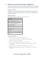
Page 13: ...n Boot Sequence The information in the boot sequence includes the following Start Up Checklist Confirm power is correctly connected to the display Confirm there is sufficient power according to displa...

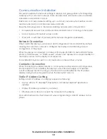
Page 14: ...and eliminating manual configuration of the player When the display is connected to a network that supports DHCP a default DHCP name similar to DMP8 xx xxxx or DMP5 xx xxxx where xxxx represents a un...

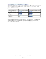
Page 15: ...is listed below with its manual number These are the standard communication types but each site is unique and may include additional equipment If problems arise contact the display s service company...

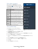
Page 16: ...required only for the first time login to VCS 4 Update the account information fields in the User Information and Additional Information sections and click Save Logging In Customer Local Hosted Serve...

Page 17: ...tisers Users Lists current user profiles and allows users to update passwords or add new users Displays Lists all available displays and provides basic management tools including Devices for linking D...

Page 18: ...under the user name to open the contact information window Refer to Figure 13 If further assistance is required Daktronics Customer Service is available 7 a m to 7 p m CST Monday to Friday via telepho...

Page 19: ...lay Access 1 Disconnect power to the display 2 Remove the bottom two modules from the second column on the left side of the display with a 1 8 hex head wrench A component layout is shown in Figure 14...

Page 20: ...wing for ventilation requirements Fans help bring fresh air into the display while exhausting hot air through the upper vents Fans are controlled via a thermostat in the display cabinet The thermostat...

Page 21: ...dry soft terry cloth towel horizontally across each row of LEDs Make four passes per row of LEDs before moving to the next row of LEDs Work from top to bottom safely within reach from a lift or a stag...

Page 22: ...ws an example of how power is routed through the display 1 AC Power enters the display through the J box on the rear of the display 1 2 Power then travels to the Power Termination Panel 2 3 Power is d...

Page 23: ...A on the first Module 3a and travels from module to module via SATA cables 3b Refer to Figure 20 Signal returns to the Controller SATA B jack 3c 4 In 2V displays signal from the primary display face...

Page 24: ...ment display To put the PLR into self test mode loop a SATA cable between ports A and B Then take a fiber cable and connect the fiber ports together Refer to Figure 22 Once the cables are connected cy...

Page 25: ...conds Module Self Test If a module is blank but has power supplied to it perform a module self test to diagnose a module or signal cable failure To perform a self test follow these steps 1 Attach a si...

Page 26: ...isconnect the power cable 5 Carefully disconnect the two signal cables from the module 6 Connect the two signal cables to the new module 7 Connect the power cable 8 Insert the tabs at the bottom of th...

Page 27: ...nt of the controller Note Do not allow the modules to hang by their cables 2 Disconnect the cables from the controller 3 Loosen the screw securing the controller enclosure and bracket 4 Carefully lift...

Page 28: ...received mail the old part to Daktronics If the replacement part fixes the problem send in the problem part which is being replaced a Package the old part in the same shipping materials in which the r...

Page 29: ...tem carefully to prevent damage during shipment Electronic components such as printed circuit boards should be placed in an antistatic bag before boxing 4 Enclose Your name Address Phone number The RM...

Page 30: ...This page intentionally left blank...

Page 31: ...ock Diagram GT6X DMP 3PLR 6 Mods Tall DWG 4285175 Block Diagram GT6X DMP 4PLR DWG 4285176 Block Diagram GT6X DMP 5PLR DWG 4285177 Block Diagram GT6X DMP 6PLR DWG 4285178 Block Diagram GT6X DMP ONE MOD...

Page 32: ...Daktronics Warranty and Limitation of Liability 28...

Page 33: ...Daktronics Warranty and Limitation of Liability 29 B Daktronics Warranty and Limitation of Liability This section includes the Daktronics Warranty Limitation of Liability statement SL 02374...

Reviews: