background image

28 

DM-100 Controller

has just been installed or to correct time due to long power outages.

There is more than one way to get to certain LCD screens on the DM-100. One way is by using the menu and 
then using the arrows to reach the desired location, and the other is to set the time, date, and then continuing 
to enter through to the additional screens. 

Time & Temperature Display Setup

To configure the DM-100 controller for use with Time & Temp displays, use the <CLEAR/SET FUNCTION> 
key on start up. The following text is displayed on the LCD during start up:

•  Daktronics, Inc.
•  Brookings, SD
•  DM-100
•  ED-13374 VX.X

The controller then lists the 

Current Function

. If it is set for 

Time and Temp

 you can continue, if not, at the 

next frame press the 

Clear/Set Function

 button and use the up and down arrows to select Time and Temp.

Note: 

Press the 

Clear/Set Function

 key quickly to enter 

Function

 mode. If you miss this step, unplug the 

power to the DM-100 controller and start again.

Note: 

The actual Time & Temperature values will not be displayed on the DM-100 LCD because these values 

are kept in the display itself.

LED Screen

Action

Press the 

Up

 and 

Down Arrow

 keys until the time and temp option is 

shown. Press the 

ENTER

 key to accept.

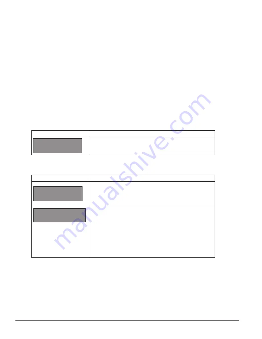
SELECT FUNCTION

TIME AND TEMP 

↑↓

LED Screen

Action

CURRENT FUNCTION

TIME AND TEMP

For indoor installation only:

 Plug the wall pack transformer into a 

120 VAC power outlet, and connect it to the handheld 

controller

.

This display appears briefly.
This message appears next on the screen. 

If TIME and TEMP Is shown on the bottom line of the LCD during 
startup, do nothing. The controller automatically defaults to previous 
Time and Temp settings. (The controller will remember the last function 
used, so you should only have to do this with a new controller.)

You only have 1 or 2 seconds to push it. If you miss it you have to 
unplug power and try again.

CHANGE FUNCTION?

PRESS SET FUNCT

Summary of Contents for DataTime DF-1012

Page 1: ...1 201 Daktronics Drive PO Box 5128 Brookings SD 57006 tel 800 843 5843 fax 605 697 4700 www daktronics com DataTime DF 1012 Time Temperature Display Installation and Operation Manual DD2563927 Rev 02...

Page 2: ...rrors or omissions No part of this book covered by the copyrights hereon may be reproduced or copied in any form or by any means graphic electronic or mechanical including photocopying taping or infor...

Page 3: ...ounding Connections 7 3 4 Power Installation 8 Installation With Ground and Neutral Conductors Provided 8 Installation With Only A Neutral Conductor Provided 8 3 5 Lightning Protection 8 3 6 Signal Co...

Page 4: ...Temperature Display Setup 28 Menu Items 29 Daylight Savings Setting 29 Set Time 29 Set Date 30 Degrees F Temperature Offset 30 Set Degrees C Temperature Offset 31 Time Temperature Format Hold Settings...

Page 5: ...ervice please have this information available to ensure that a request is serviced as quickly as possible 1 2 Product Overview DataTime Time Temperature displays show temperatures in Fahrenheit or Cel...

Page 6: ......

Page 7: ...e DataTime displays are designed for wall or pole mounting every installation is different Actual site demands dictate the appropriate mounting method DataTime DF 1012 models are designed to be insert...

Page 8: ...erature information Both temperature and light monitoring electronics are located in the sensor housing shown in Figure 2 The Daktronics Controller Area Network CAN Temperature Light Sensor is pre ins...

Page 9: ...et vertically between the sensor and the influential element Locations that restrict air movement are also unsatisfactory When a display has two faces do not mount the sensor between the faces Connect...

Page 10: ...eater than the provided 25 foot 7 6 m cable connect a 4 conductor shielded cable from the sensor to TB1 on the display driver board 1 The display s power must be OFF when attaching the internal sensor...

Page 11: ...al installation 3 2 Power Connections Daktronics DataTime displays have removable or hinged front panels that allow access to the digits cabling and other electronic components DataTime outdoor displa...

Page 12: ...isolated earth ground conductor In this circumstance do not connect neutral to ground at the disconnect or at the display as this would violate electrical codes and void the warranty Use a disconnect...

Page 13: ...ated as the host driver which receives its signal directly from the DataMaster controller on its Signal IN terminals It is the only driver that is connected to the photo temperature sensor The Signal...

Page 14: ...protocol jack J20 3 Route a six conductor 18 AWG shielded signal cable through conduit from the J box to the driver enclosure in the host display Fifty feet 15 2 m of signal wire is provided 4 Connec...

Page 15: ...need to be connected to the J box and a wall pack transformer will be used for power to the DataMaster controller The distance from the indoor J box to the host driver can be up to 2 000 ft 600 m Ref...

Page 16: ...ect to the client drivers Refer to Figure 12 and Drawing A 185236 for an illustration of the client host display connection Client drivers receive signal from the host driver on SIGNAL OUT J1 24VDC RA...

Page 17: ...e of information is shown on the driver s digits The switch is set using a binary address Use the table and the examples in Figure 13 for setting the address Note Some older drivers set the address of...

Page 18: ......

Page 19: ...Surge Board Signal Power Input Termination Jacks On 10 and 13 displays all the components are behind one door For 18 and 24 displays the hinged doors swing outward when the two latches on the front di...

Page 20: ...protocol plug is not connected Protocol plug for host driver only Check addressing of client display Client drivers will continually cycle through the power on self test host driver Make sure address...

Page 21: ...e case either the wrong address is set or the driver or digit harness is connected incorrectly If no address is set on the host driver it will display E5 and all client drivers will continually cycle...

Page 22: ......

Page 23: ...ssion board 0P 1110 0011 Driver 4 Column 0P 1192 0068 DM 100 Controller parts DM 100 handheld controller 0A 1196 0088 Junction box outdoor 9 pin D male 0A 1196 0093 Junction box indoor 9 pin D male 0A...

Page 24: ...constructed in segments as shown in Figure 16 In this case make repairs by removing only the defective segment Do not attempt to remove individual LEDs To remove a digit segment follow these steps 1...

Page 25: ...cation of the driver All DataTime displays are front accessible 1 Open the digit panel or display face panel as described in Section 4 1 2 Remove the cover from the driver enclosure 3 Label all cables...

Page 26: ...in Section 4 1 2 Remove the cover from the driver enclosure 3 Disconnect the power connector from the surge board Release it by squeezing together the locking tabs and pull the connector free Note Whe...

Page 27: ...ler Refer to Drawings A 938300 for the location of the surge board inside the driver enclosure The surge board is pre wired before the display is shipped Note The surge suppressor must be firmly conne...

Page 28: ......

Page 29: ...part fixes the problem send in the failed part within 3 weeks of the ship date a Package the old part in the same shipping materials in which the replacement part arrived b Fill out and attach the en...

Page 30: ...d be placed in an antistatic bag before boxing Daktronics does not recommend using packing peanuts 4 Enclose your name address phone number the RMA number a clear description of symptoms Shipping Addr...

Page 31: ...mation for the displays To see more detail on the DM 100 insert refer to drawing A 164998 If an insert is lost or damaged a copy of the insert drawing can be used until a replacement is ordered To sta...

Page 32: ...on key quickly to enter Function mode If you miss this step unplug the power to the DM 100 controller and start again Note The actual Time Temperature values will not be displayed on the DM 100 LCD be...

Page 33: ...key to accept Press the down arrow key to select the Enable or Disable Daylight saving time correction If enabled the display time automatically corrects for daylight saving time The default setting...

Page 34: ...or decrement the Fahrenheit temperature value read from the temperature sensor LED Screen Action MM Current month DD Current day YY Current year last two digits Input the month MM using the number key...

Page 35: ...ve humidity RH is available on the DM 100 controller but cannot be read using the standard temp light sensor LED Screen Action 00 shows the current degrees Celsius temperature offset Press the Up and...

Page 36: ...tings The DM 100 controller has an option to set modem settings but this method of communication is not used with standard Time Temp Displays If a modem was used the next screen would require the user...

Page 37: ...key to toggle through dim settings Automatic The display automatically dims based on the light detected at the display Manual The dimming level is set manually Once set this value remains regardless...

Page 38: ......

Page 39: ...work The address is set using an 8 position binary switch For single line signs such as a Time Temp display the address will typically be 1 The address will be displayed each time the display powers u...

Page 40: ......

Page 41: ...trol Drawing A 175342 Time Temp Power Signal Hookup Drawing A 938369 Installation Temp Sensor G3 Drawing A 184840 Enclosed Driver 4 Column Reference Drawing A 938300 Host Client Definitions Drawing A...

Page 42: ......

Page 43: ...Appendix B Temperature Sensor Mounting 39 Appendix B Temperature Sensor Mounting ED 18601 Temperature Sensor Mounting ED 18601...

Page 44: ......

Page 45: ...Appendix C DataTime Quick Installation Reference 41 Appendix C DataTime Quick Installation Reference A 176249 Installation Quick Reference DF 1012 Time Temp Drawing A 176249...

Page 46: ......

Page 47: ...Appendix D DataTime Quick Start Reference 43 Appendix D DataTime Quick Start Reference DD2563921 DataTime Time Temperature Quick Start Reference DD2563921...

Page 48: ......

Page 49: ...Appendix E Warranty and Limitation of Liability 45 Appendix E Daktronics Warranty and Limitation of Liability SL 02374...

Reviews: