


1
Introduction
Section 1: Introduction
This manual provides the necessary information to install and fire-up a Daktronics digital billboard.
Please read and understand all steps in this manual before beginning the installation process. Contact the
Project Manager with any questions.
1.1 Limitation of Liability
Failure to perform the following may null and void any factory warranties:
• Install the digital billboard according to the steps in this manual.
• Provide proper electrical service.
• Ground the display properly.
For the full
Daktronics Warranty and Limitation of Liability, refer to Appendix B at the end of
this manual.
1.2 Important Contact Information
Daktronics Help Desk: 1-877-DAK-HELP
Project Manager:
1.3
Display Identification
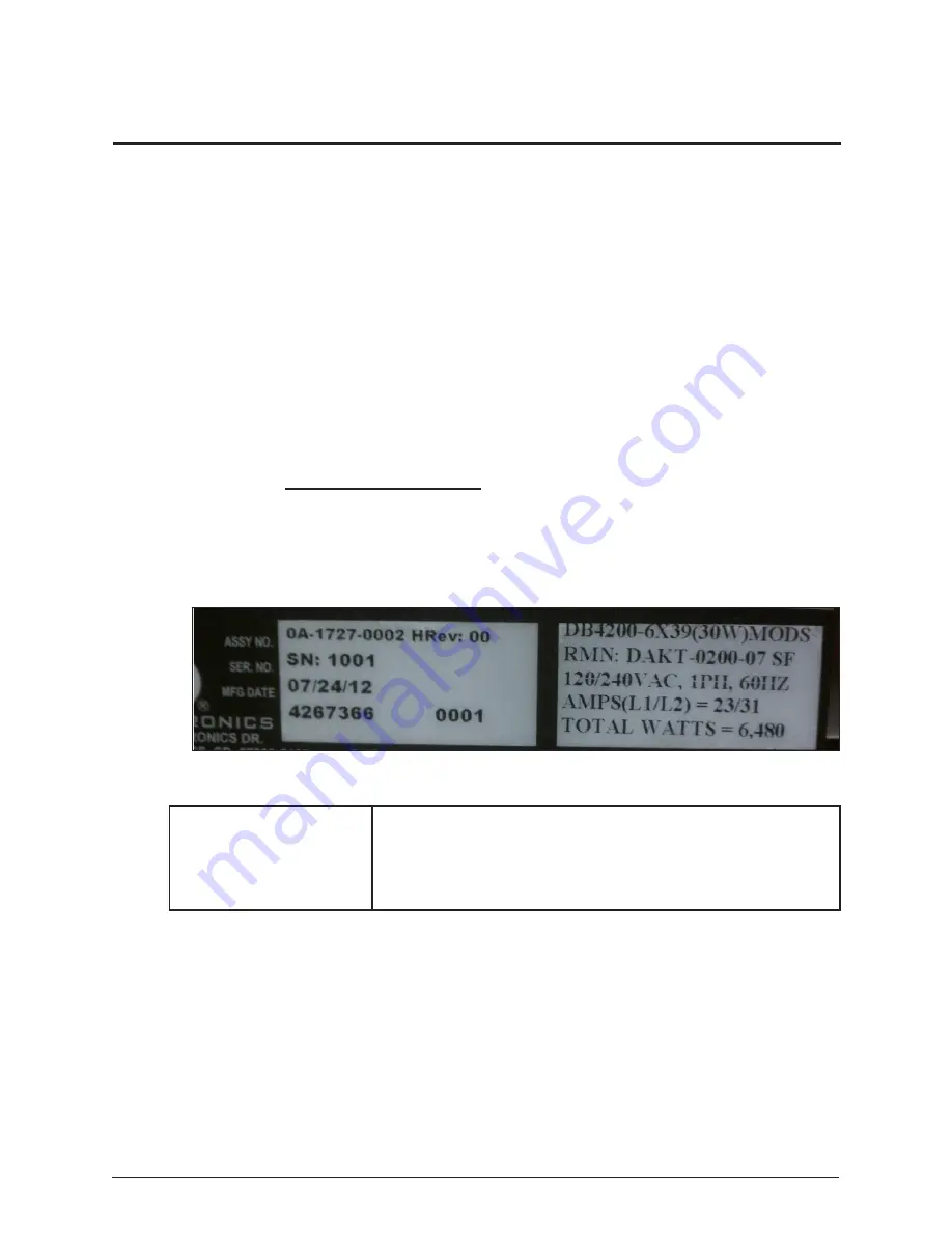
This section provides label information that is helpful in understanding a Daktronics digital
billboard display label. Refer to the circled area in
Figure 1 while reading the table below.
Display Assembly Number
Display Serial Number
Manufacture Month/Date/Year
DB-4200 Modules High X Modules Wide (Module power in Watts) MODS
RMN: Daktronics - 0200 - 07 Manufactured in Sioux Falls, SD
120/240 VAC, Single Phase, 60 HZ
AMPS (L1/L2) = 23/31
Total Watts for Display Section = 6,480
Figure 1:
4200 Series Display Label
Summary of Contents for 4200 Series
Page 10: ......
Page 12: ......
Page 16: ...12 Display Installation ...
Page 20: ...16 Section Splicing ...
Page 22: ...18 Multi Direction Light Sensor Relocation ...
Page 26: ......
Page 28: ......
Page 30: ......
Page 34: ...30 First Time Power Up ...
Page 36: ...32 Display Testing and Adjustment ...
Page 38: ...34 Reference Drawings ...


