background image

2

I. Monitor Introduction

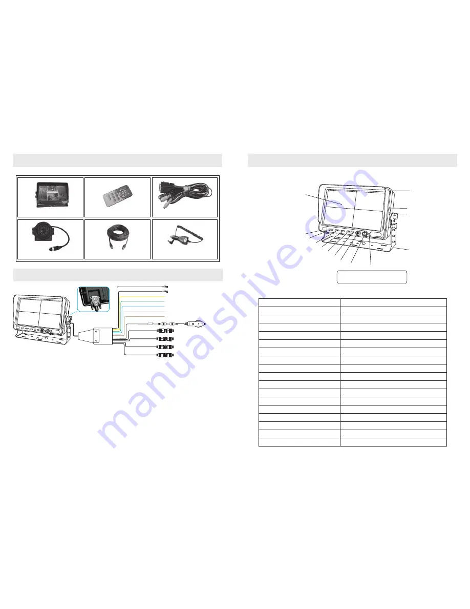
Monitor

II. Specifications

Included Components

CDS

Sensor for controlling the button

backlights. DO NOT BLOCK

Sun


Visor

A/V


output

Earphone

Bracket

MENU

Remote


Receiver

Vol-

Vol+

Menu

Down

Up/CAM Selection

Quad View Mode Switch

ON/OFF

LED Backlit

LCD


Screen

Monitor

LED backlit, Digital Screen TFT LCD Color

Size


7 Inch

Connector

Digital TTL  

Resolution

800(RGB)

×

480 

No. Camera Inputs

4

Visible


Angle (LR/UD)

140 / 110 

Contrast

500:1 

Volume (nits)

300 

Response Time (ms)

25 

Color System

PAL/NTSC (AUTO) 

Support Four Camera Inputs

1.0Vp-p75Ω 

Audio


Output

W

1W

Loudspeaker

φ

4

.

0cm,16Ω/1W

Connector

DVI24+1

 Power Source

DC11-32V Free Power Input

Consumption

MIN  8W, MAX 20W (four cameras


ON)

External dimensions(mm)

185 X W 124 X T48 (without mounting) 

Weight

400g

9

Monitor remote control

Power/Video harness

Monitor w/ bracket

Connection


Chart

MENU

(Yellow)Video Output

(Red)  Audio Output
(Yellow*)Trigger Cable for DVR
(Green*)Trigger Cable for CAMF
(Blue*)Trigger Cable for CAMR
(White*)Trigger Cable for CAML
(Brown*)Trigger Cable for CAMB

DVI24+1Plug


connector


with


screws

CAM F (Black)

CAM B (Yellow)

CAM L (White)

CAM R (Red)

12v power

FUSE

12v lighter adaptor

x2 20M power/video cables

x2 Camera(s) w/ bracket

1) Cameras 1-4 have an available event trigger wire. Cameras are identified as F (front), B (Back), 

    L (Left) and R (Right)

2) Regardless if monitor is ON or in Standby mode, if power is applied to the trigger, activated camera

    will become powered

3) Camera F has highest priority, camera R the lowest. Example: if both camera F and B are triggered

    simultaneously, camera F will take precedence.

4) Peripheral DVR trigger cable

     1. When the monitor is in quad view or front and back view, the cable has a DC12V output.  

     2. When the back trigger cable makes the monitor activated, the peripheral DVR trigger 

         cable has a DC12V output

* Event Trigger wire colors are subject to change without notice and may vary slightly from


colors indicated above

.

Summary of Contents for OverView DMOV-7MQ-C2

Page 1: ...al inverted picture Check horizontal vertical adjustment on remote No car backing function i e Picture Event trigger is not securely connected Remote Controller Fault Battery may be dead or improperly installed replacement battery Model CR2025 3V Remote controller is not pointed in the direction of the receiving sensor Make sure remote is pointed at the monitor Long distance or improper angle The ...

Page 2: ...nship and materials and agrees that it will at its option either repair the defect or replace the defective product or part thereof with a new or remanufactured equivalent at no charge to the purchaser for parts or labor for the period of 18 eighteen months Warranty extends throughout North America US Canada 1 year warranty applies to all other geographic locations unless otherwise states in writi...

Page 3: ...w Video Output Red Audio Output Yellow Trigger Cable for DVR Green Trigger Cable for CAMF Blue Trigger Cable for CAMR White Trigger Cable for CAML Brown Trigger Cable for CAMB DVI24 1Plug connector with screws CAM F Black CAM B Yellow CAM L White CAM R Red 12v power FUSE 12v lighter adaptor x2 20M power video cables x2 Camera s w bracket 1 Cameras 1 4 have an available event trigger wire Cameras a...

Page 4: ... Remove Sunshade Monitor Monitor with sunshade press press Pull monitor sunshade Push Push monitor with sunshade Complete IV Install Remove Sun Visor 8 Monitor MENU Camera Image pick up Device TV System Lens Mount Horizontal Resolution Sync System Number of Pixels Usable Illumination Operation Temp Power Supply Weight Environmental 1 3 Sharp Color CCD NTSC PAL depending upon model 420 TV lines Int...

Page 5: ...ATION HUE SELECT ADJUST 50 50 50 50 50 MENU Vol Vol Menu Down Up CAM Selection Quad View Mode Switch ON Standby 1 Press ON Standby to turn monitor ON OFF 2 Quad View Mode Switch Turn monitor on and press Quad View Mode Switch key the quad view will be changed as below one by one 3 Up CAM Selection a After pressing the Menu key press the Up CAM Selection to select menu and set up b To switch the im...

Page 6: ...rmal Mirror Image Monitor displays Camera function as listed below SELECT ADJUST CAM B CAM L CAM R CAM F NORMAL MIRROR MIRROR MIRROR MIRROR CAM B CAM L CAM R CAM F c TRIGDELAY Monitor displays camera function as listed below SELECT ADJUST TRIG DELAY Press Up Down to select CAMB CAML CAMR CAMF press Vol to set up Normal Mirror image of CAMB CAML CAMR CAMF Press Up Down to select CAMB CAML CAMR CAMF...

Reviews: