


4
There
are
2
lengths
of
cable
with
your
camera
system:
One
(1)
20’
and
one
(1)
60’.
The
20’
cable
is
to
be
used
to
route
from
the
cab
to
the
hitch
of
your
tractor.
The
60’
can
be
used
to
run
from
the
hitch
end
of
the
implement
(air
seeder
for
example)
to
the
camera
mounting
location.
This
will
allow
for
easy
separation
of
the
tractor
and
implement
without
having
to
remove
the
camera.
If
the
camera
is
to
be
used
on
a
truck
or
other
vehicle,
the
20’
or
the
60’
cable
may
be
sufficient.
Therefore,
extra
cable
will
not
be
needed.
If
you
would
like
to
purchase
different
or
additional
cable
lengths,
please
contact
your
dealer
where
you
purchased
your
AgCam®.
Cable
Warnings
•
Cable
routing
is
important.
Where
you
chose
to
run
the
cables
should
not
interfere
with
the
normal
operation
of
the
machine
or
any
safety
equipment.
•
ALWAYS
be
aware
of
any
“pinch
points”
or
other
potential
hazards
to
the
cable.
•
Secure
all
cables
to
vehicle/equipment
using
included
cable
clips,
zip
ties
or
other
style
fastener.
•
If
you
intend
to
use
your
AgCam®
for
short
length
PTO
operated
implement,
avoid
excess
cable
lengths
if
possible.
When
you
decide
on
a
location
you
should
fix
the
camera
to
a
permanent
bracket
using
¼
inch
bolts,
and
attach
any
loose
cable
securely
so
there
is
no
chance
of
entanglement
in
the
PTO
or
other
moving
parts.
•
If
you
use
your
AgCam®
to
monitor
a
combine
hopper
or
other
combine
operations,
take
care
to
remember
that
combines
have
many
moving
parts.
Use
extreme
care
when
routing
cables,
and
it
is
strongly
recommended
that
you
use
bolts
to
secure
the
camera.
While
it
would
be
sufficient
to
use
the
magnetic
base
for
monitoring
purposes
during
road
travel,
it
is
advised
to
secure
the
camera
with
bolts
during
operation
of
the
combine.
c.
Monitor
Installation
&
Mounting
Mounting:
Remove
your
monitor
carefully
from
packaging,
and
inspect
all
mounting
hardware.
Mounting
location
is
the
most
important
part
of
the
monitor
installation
to
ensure
maximum
visual
benefit
from
your
AgCam®
system.
Keep
in
mind:
•
Least
direct
sunlight.
Keeping
your
monitor
out
of
direct
sunlight
will
prolong
the
life
of
the
unit
as
well
as
ensure
optimum
visibility
•
Does
not
obstruct
your
view
•
Does
not
interfere
with
the
normal
operation
of
vehicle
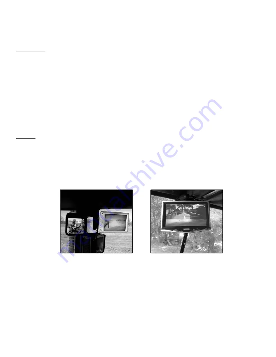
Examples:
Tractor
w/
air
seeder
in
tow
Grain
Truck
Dry
mount
the
monitor
to
the
included
universal
mounting
bracket
by:
1.
Sliding
the
square
mounting
stud
on
top
of
mounting
bracket
into
the
slot
on
back
of
the
monitor.
2.
Tighten
nut
by
turning
the
knob
on
the
back
of
mounting
bracket
clockwise.
(Optional
style
monitor
brackets
are
available:
suction
cup
style
and
hard
mount.
Both
of
these
style
brackets
have
a
square
mounting
stud
as
well).
Once
you
have
attached
the
monitor
to
the
mounting
bracket,
follow
these
steps
to
finalize
the
installation.
1.
With
the
mount
and
monitor
attached,
find
and
mark
the
desired
position
for
the
monitor.
2.
Remove
the
monitor
from
the
mount.
3.
Thoroughly
clean
the
intended
mounting
location
with
alcohol
prep
wipe
or
other
non
‐
oil
based
cleaner.
4.
Remove
the
paper
backing
from
the
stand
and
press
firmly
in
desired
location.
5.
If
mounting
in
other
than
a
flat,
level
location,
use
small
screws
in
the
four
corners
of
the
mounting
bracket
to
permanently
secure.


