background image

Dakota Micro, Inc.


AC

-

9MQ(‐C2) User Manual


Rev: 06/26/17                                           Page 3 of 12


Author: CNR 


B.   Monitors 


Feature the latest in LCD technology.  


View 1, 2, or 4 cameras at the same time; also includes two (2) different Quad views.  


Include event triggers for each camera input. 


Color, brightness, contrast and volume controls that allow compensation for use in different environments. 


Remote control, sun shield, and metal U‐bracket included. 

C.   Cables 


Silicone jacket enables high flexibility in all temperatures. 


Our durable power/video extension cables come in 20’ and 60’ standard lengths and feature sturdy, 
watertight connectors.  


Additional power/video cables available in the following lengths: 

10’, 30’, 40’, 50’ & 80’.


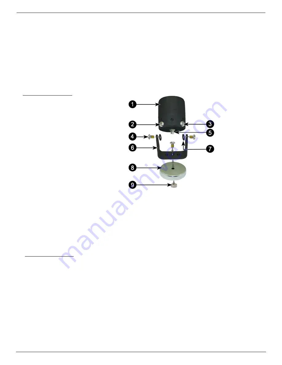
III.   PARTS OF AN AGCAM 


A.   Camera  

1.


Camera Body 

2.


IR Function Plug 

*


3.


MIR Function Plug

*


4.


Retaining Screw (x3) 

5.


Camera Tail Input 

6.


Camera Bracket 

7.


Fiber Washer (x2) 

8.


Magnet 

9.


Magnet Nut 


*

Function Plugs (Elite Models Only) 


There are two (2) function plugs on the bottom of each Elite AgCam

® 

camera, near the camera tail. They will look 

like two (2) additional screws at a slight angle recessed into the camera body. The function plugs utilize a polarized 
magnet to change camera functionality. 


IR ON/OFF

 ‐ This function plug requires a magnet to allow for the IR LED’s functioning in low light 

conditions. If you remove the polarized magnet, the IR LED’s will 

NOT

 come on. 


MIR/FOR

 ‐ This function requires a magnet to activate/deactivate the mirror/forward function of the 

camera. Elite cameras are shipped from the factory with the MIR magnet installed. 
 

IV.   CAMERA MOUNTING 

After camera is securely mounted, plug the camera pigtail into rear of AgCam® camera. You can now plug the remaining 
end of the pigtail into your power/video extension cable. Make sure the extension cables are securely attached and locked 
(¼ turn will lock the cables together). 


A.   Temporary Mounting  

o


For temporary mounting, it is recommended that you use the supplied 65# pull magnet. If using magnetic 
mount, fasten camera cable with a zip tie or other style fastener. This will act as a “safety wire” in the event your 
camera is knocked loose for some reason. When selecting a location, make sure that the equipment surface is 
clean of all foreign material and as flat as possible to ensure that the magnetic camera base will have good 
contact and not vibrate off. 

B.   Permanent Mounting 

o


For permanent mounting, it is recommended that you remove the magnet and attach to any solid surface with 
two (2) screws.   


C.    Suggestions for Camera Mounting 

Summary of Contents for AC-9MQ

Page 1: ...ing Tips Warnings 4 VII Monitor Installation Mounting 4 5 A Mounting Precautions B Universal Bracket Mounting C Finalizing Universal Bracket Installation VIII Installation 5 A Monitor Wire Harness Det...

Page 2: ...es available include 6mm 12mm 16mm A complete lens guide is available on our website Function plugs on Elite AgCam versions allow for IR ON OFF and switching of forward reverse image Removable replace...

Page 3: ...change camera functionality IR ON OFF This function plug requires a magnet to allow for the IR LED s functioning in low light conditions If you remove the polarized magnet the IR LED s will NOT come o...

Page 4: ...able lengths please contact your local AgCam dealer A Cable routing is important where you choose to run the cables should not interfere with the normal operation of the machine or any safety equipmen...

Page 5: ...r 1 Attach the power input connector 3 above to your included 12v cigarette lighter adaptor 2 Plug cigarette lighter adaptor into 12v power source B Hardwire Power Adaptor 1 If you would like to hardw...

Page 6: ...switch from channel 2 3 or 4 to channel 1 when the auger is extended The event circuit should be neutral in its normal state and change to HIGH 12v when the event is considered to be active XI REMOTE...

Page 7: ...own Navigation Arrows MENU Enters the menu Also acts as enter button in menu settings MODE Adjusts screen display modes RESET Reset your selection TIMER Enables timer that will turn off monitor GRID S...

Page 8: ...o change the value of the highlighted item 4 To exit Press the or key on the monitor left or right arrow on remote multiple times until the menu goes away Allow monitor to time out approximately 5 sec...

Page 9: ...nit to factory preset options DISPLAY SETUP DISPLAY ON SCREEN Press ENTER to select what information is displayed on screen SCREEN POSITION X Use the right arrow and the left arrow to move the screen...

Page 10: ...Vp p 75 Ohms Operating Temp 45 F 150 F 42 C 66 C Construction Aluminum Case Waterproofing criteria IP 68 69 Dimensions 53x58 L mm Body Only B LCD Monitor Screen Size 9 16 9 digital panel Overall Size...

Page 11: ...deemed necessary Technician will issue a Repair Authorization RA number IMPORTANT NOTE The Technician will note if the repair APPEARS to be a warranty or non warranty issue based on customer descripti...

Page 12: ...ights under this limited warranty the purchaser should follow the steps set forth in the complete Dakota Micro Warranty Repair Policy listed on page 11 section XVI and provide proof of purchase to Dak...

Reviews: