


page 3
MAN#650265
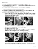
a. Turn the provided dual terminal pressure sensor into female end of pressure sensor extension assembly and
tighten with appropriate wrenches. Teflon tape or similar sealant may be used to ensure a leak free installation.
b. Locate and remove the plug from the pressure check port on the front of the engine.
c. Turn the pressure sensor extension assembly into the port and tighten with a wrench. Again, sealant or tape
may be used here to prevent leaks.
d. Using the provided hose clamp, clamp the sensor
body to the seat support frame rail. Check that the
sensor will not prevent reinstalling the seat.
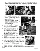
e. Remove the two thumb nuts and lock washers from
the terminals on the sensor.
f.
Place the one ring terminal from the provided
wiring harness onto each of the terminals on the
sender and secure with the lock washer and thumb
nut. Polarity doesn’t matter so the wires can
connect to either terminal.
g.
Be sure to check engine oil level and add oil if
needed
.
7. Route the wiring harness from the sensor locations
along the seat support frame rail securing with
provided plastic ties over to the drivers side of the
vehicle.
8. Continue to route the harness under driver’s side
floor along the vehicles main harness. Take care
to keep the harness away from pinch points or
moving parts like the drive shaft.
9. Route the harness up in front of the front cab
panel and up to the gauge opening. Secure
where needed with provided plastic ties. Sensor
pack installation is now complete. See
“ENABLING TEMP OIL DISPLAY” in setup notes.
10. Position the provided gauge dash cushion ring onto the back of the
UTV-1500.
11. Plug the main gauge harness connector, the speed connector and the
sensor harness connector (if used) into the back of the UTV-1500.
12. Place the UTV-1500 into the gauge opening while lining up tab on
gauge with the notch in the dash opening.
13. Secure the gauge by placing the provided “L” clamps over the two studs
on the back of the gauge with the long legs against the back side of the
dash. Secure the clamps and gauge with the provided thumb nuts.
14. Connect battery, turn the key on and verify gauge operation.
15. Start engine and check for oil and water leaks. Shut off engine.
16. If there are no oil or water leaks, reinstall any previously removed floor
panels, engine covers and seats as described in the service manual.
17. Installation is now complete. If you experience difficulties check the troubleshooting section in this manual.
SETUP
(Step 6c)
(Step 6b)
(Step 6a)
(Step 6d)
(Step 7
and
Step 8)
(Step 12)