background image

Dake Corporation 

724 Robbins Road  

Grand Haven, MI 49417 

www.dakecorp.com


  25 

REV032019 


Item 

Part Name 

Part No. 

74 

Handgrip with Switch 

44600001 

81 

Blade Shaft Flange 

AF710163 

82 

Screw M12 x 35mm left thread 

S1110136 

83 

Fixed Blade Guard 

AGB90085 

84 

Dowel M8 x 30mm 

81132081 

85 

Front Head Cover 

AGB90002 

86 

Coolant Distributor 

AFB80055 

87 

Coolant Hose 

69102002 

88 

Dowel M6 

64179 

89 

Mobile Blade Guard 

160C0063 

90 

Snap Ring Ø60E 

82600000 

91 

Mobile Blade Guard Pin 

160C0063 

92 

Socket Cap Screw (M6 x 12mm) 

80625 

93 

Tie Rod Support 

AFB90087 

94 

Socket Cap Screw (M6 x 12mm) 

80625 

95 

Socket Cap Screw (M6 x 12mm) 

80625 

96 

Tie Rod Mobile Guard 

AFB90088 

97 

Snap Ring Ø10E 

98 

Tie Rod Support Pin 

AF19B090 

100 

Ring Nut (GUK M20 x 1mm) 

81700020 

101 

Worm Screw 

AFB90015 

102 

Worm Screw Spacer 

AFB90017 

103 

Snap Ring SEEGER Ø42  

82610000 

104 

Bearing 3305 

84301010 

105 

Oil Seal 

301959 

106 

Ring OR 4312 

302920 

107 

Front Motor Flange 

N/A 

108


In motor assembly


-


110 

In motor assembly 

-


111 

In motor assembly 

112 

In motor assembly 

113 

In motor assembly 

115 

O-Ring 

86002004 

117 

In motor assembly 

119 

In motor assembly 

120 

Bearing 4205 

84130010 

121 

Motor Fan 

74310007 

Summary of Contents for Technics 350 CE

Page 1: ...ww dakecorp com customerservice dakecorp com DAKE MANUAL COLD SAW Technics 350 CE Frequency driven motor only INSTRUCTIONAL MANUAL WARNING Read and understand all instructions and responsibilities before operating Failure to follow safety instructions and labels could result in serious injury ...

Page 2: ...ANCHORING 9 ELECTRICAL CONNECTION 9 ASSEMBLING THE MACHINE 10 CHOOSING A BLADE 10 OPERATION 11 STARTING AND CUTTING 12 MAINTENANCE 13 ROUTINE MAINTENANCE 13 CHANGING THE BLADE 14 REGULATING ARM BLOCKAGE 14 CHANGING COOLANT PUMP 15 CHANGING THE GEAR BOX OIL 15 TROUBLESHOOTING 16 ELECTRICAL DIAGRAMS 19 EXPLODED VIEW 21 PARTS LIST 23 ORDERING INFORMATION 26 DEACTIVATING THE MACHINE 27 DISMANTLING THE...

Page 3: ... manufacturer will repair or replace any portion of the product that proves defective in materials or workmanship The manufacturer retains the sole right and option after inspection to determine whether to repair or replace defective equipment parts or components The manufacturer will assume ownership of any defective parts replaced under this warranty All requested warranty claims must be communi...

Page 4: ...tion or failure to operate or maintain the unit in accordance with the printed instructions provided c Defects or malfunctions resulting from abuse accident neglect or damage outside of prepaid freight terms d Normal maintenance service or preventative maintenance and the parts used in connection with such service e Units and parts which have been altered or repaired other than by the manufacturer...

Page 5: ... Customer Service a representative will supply a Return Material Authorization RMA number The returned item must have the provided RMA number clearly marked on the outside packaging Any item received without an RMA number clearly visible on the packaging will not be processed An RMA number can only be provided by the Dake Customer Service team and must be obtained prior to the return shipment Refu...

Page 6: ...ght for slots Phase 3 Weight 650 lbs Horsepower 3 5 HP Work Height 40 Speeds 22 88 RPM Height 79 Max blade diameter 14 Base 27 x 39 CUTTING CAPACITY 90 3 3 8 4 3 4 4 1 8 6 1 4 x 3 1 2 45 2 7 8 4 3 3 8 3 3 8 x 2 3 4 In the space provided record the serial number and model number of the machine If contacting Dake this information must be provided to assist in identifying the specific machine Serial ...

Page 7: ...be alert to the potential for personal injury Carefully read all safety messages in these instructions and on your machine safety signs Keep safety labels in good condition Replace missing or damaged labels Employer is responsible to perform a hazard PPE assessment before work activity Label Part No 84605 Label Part No 84395 Label Part No 76462 Label Part No 82199 ...

Page 8: ...at the voltage indicated on the plate normally fixed to the machine motor is the same as the line voltage Check the efficiency of your electric supply making sure the machine has its own grounded circuit Do not operation machine without safety guards or with the electrical panel cover removed Then the tool head is in rest position raised the toothed blade must be stationary Always disconnect the m...

Page 9: ...irect or indirect contact The active parts of this equipment are housed in a box so that access is limited by screws can only be removed with a special tool the parts are fed with alternating current at low voltage 24V This equipment is protected against splashes of water and dust Protection of the system against short circuits is ensures by means of rapid fuses and earthing in the event of motor ...

Page 10: ...o the ground using screws and expansion plugs or tie rods sunk in the cement ensure it is sitting level before anchoring Minimum requirements for working environment of the machine Main voltage and frequency complying with the machine motor characteristics Environmental temperature from 15 F to 120 F 10 C to 50 C Relative humidity no higher than 90 ELECTRICAL CONNECTION The machine is not provided...

Page 11: ...h and align the work support bracket on the left hand side of the saw base using the two bolts provided CHOOSING A BLADE The saw will come with a DAKE Saw Pitch Calculator to assist in blade selection First the pitch of the teeth must be chosen suitable for the material to be cut according to these criteria Parts with a thing and or variable section such as profiles pipes and plates need fine toot...

Page 12: ...chine it is recommended to start using it in intervals of a half hour This operation should be repeated two or three times after this the machine may be used continuously Do not use cutting blades of a different size from those stated in the specifications section If the cutting blade gets stuck in the work piece release the blade ON button immediately switch off the machine and open the vise slow...

Page 13: ...utton checking that the blade is turning in the direction indicated if not invert the two phase leads and that sufficient coolant is coming out 5 Turn variable speed dial 3 to desired speed DO NOT ADJUST SPEED UNTIL BLADE IS RUNNING 6 The saw is now ready to begin cutting a When cutting with a new blade the first two or three cuts must be made while exerting a slight pressure on the part so that t...

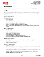
Page 14: ...he return spring WEEKLY MAINTENANCE Sharpen blade Clean blade housing Make sure the gearbox is full of oil Check power chord for any damage Clean shavings from lubricant tank Clean and grease the screw and sliding guide vise Clean the filter of the pump suction head and the suction area MONTHLY MAINTENANCE Check tightness of the screws on the motor pump jaws and safety guard Check safety shields a...

Page 15: ...ise direction as it has left handed threads 4 Slip off the flange that holds the blade in place and remove old blade 5 Install new blade on spindle and align blade drag holes with the spindle holes 6 Install flange and tighten spindle bolt tight by hand 7 Push the blade against direction of rotation until the holes deadhead against the flange drive pins and tighten spindle bolt securely This step ...

Page 16: ...Gear Oil we recommend MOBIL SHC635 1 Disconnect machine from power supply 2 Unscrew the handle and remove the plug coming out of the handle that goes to the electrical box 3 Use a bucket to collect old oil unscrew oil plug to let oil drain when finished draining replace oil plug 4 Keeping the head in the upper position pour new oil into the handle opening until it is seen half way up the sight lev...

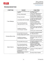
Page 17: ...ant or incorrect type of coolant Check the level of coolant in tank and increase the flow of coolant Talk to your coolant provider Premature Blade Wear Wrong blade being used Consult your blade provider for adequate blade Wrong cutting speed or feed Insufficient coolant or incorrect type of coolant Check the level of coolant in tank and increase the flow of coolant Talk to your coolant provider Bl...

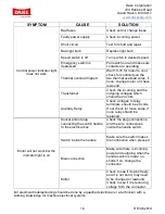
Page 18: ...ove Check the material for tightness before cutting Check the condition of the jaw faces Blade advance is too fast Exert less cutting pressure on the material Blade teeth are worn Sharpen blade or replace Insufficient coolant Check the level of coolant in tank and increase the flow of coolant Talk to your coolant provider Toothing does not unload shavings well Select a blade with a larger tooth pi...

Page 19: ...ould be 24 volts Auxiliary Relay Check voltages to relay terminals should be 24 volts If not check for loose wires if none relay should be replaced Motor will not work but the indicator light is on Socket and or plug connecting the switch handle to the electrical box Check the plug connections and the wire connections inside the handle switch Switch inside the handle Make sure the switch makes the...

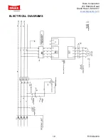
Page 20: ...Dake Corporation 724 Robbins Road Grand Haven MI 49417 www dakecorp com 19 REV032019 ELECTRICAL DIAGRAMS ...

Page 21: ...Dake Corporation 724 Robbins Road Grand Haven MI 49417 www dakecorp com 20 REV032019 ...

Page 22: ...Dake Corporation 724 Robbins Road Grand Haven MI 49417 www dakecorp com 21 REV032019 EXPLODED VIEW Exploded view is only for 350CE Cold Saw with Frequency Drive Motor ...

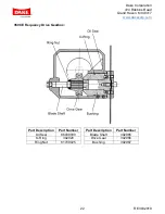
Page 23: ...and Haven MI 49417 www dakecorp com 22 REV032019 350CE Frequency Drive Gearbox Part Description Part Number Part Description Part Number Oil Seal 86000000 Blade Shaft 302965 O Ring 302920 Drive Gear 302966 Ring Nut 81700025 Bushing 302967 ...

Page 24: ...tervise Fixing Pin AFB90044 12 13 Roller Support Arm Roller 303343 14 Washer M10 43633 15 Bolt M10 81505 17 Vise cast iron AGB90055 18 Vise Jaw AFB90056 19 Vise Jaw Washer AFB8B037 20 Screw TCCE M12 81110133 21 Washer 8 5mm ID x 21mm OD 82100000 22 Screw TCCE M12 81110133 23 Dowel M8 x 30mm 81132081 24 Lever Bushing AFB80032 25 Quick Lock Vise Lever AGB80031 26 Bearing AX 3047 84500001 27 Quick Lo...

Page 25: ... Ø42 82610000 51 Tank Cover Filter 52 Tank Cover Wire Gauze 53 Tank Cover ANB80041 54 Washer 8 5mm ID x 21mm OD 82100000 55 Coolant Flow 88600000 56 Coolant Hose 69102002 57 Extra Protection 58 Spring Connection AFC10024 59 Head Return Spring AFB90034 60 Nut M12 301134 61 Screw M12 81110133 62 Head Casting AGB90001 Head Cover Gasket ANB90003 63 Oil Plug 88302002 64 Ring Nut M25 x 1 5 81700025 65 S...

Page 26: ...63 92 Socket Cap Screw M6 x 12mm 80625 93 Tie Rod Support AFB90087 94 Socket Cap Screw M6 x 12mm 80625 95 Socket Cap Screw M6 x 12mm 80625 96 Tie Rod Mobile Guard AFB90088 97 Snap Ring Ø10E 98 Tie Rod Support Pin AF19B090 100 Ring Nut GUK M20 x 1mm 81700020 101 Worm Screw AFB90015 102 Worm Screw Spacer AFB90017 103 Snap Ring SEEGER Ø42 82610000 104 Bearing 3305 84301010 105 Oil Seal 301959 106 Rin...

Page 27: ... Connector 73600005 145 Plug Connector 73600052 147 Reset Push Button 716812 148 Emergency Push Button 716538 Motor 303318 Fuse Cartridge 302977 Motor Starter 302978 Under Voltage Trip 220 240 302979 Under Voltage Trip 208 220 303276 Main Switch 302981 Frequency Drive 302843 Kit Pneumatic Vise AAB9100L Filter unit Pneumatic vise 88112015 Valve Pneumatic vise 88125000 Pneumatic Vise Cylinder 782000...

Page 28: ...ng 1 Unplug machine 2 Release the arch return spring 3 Empty coolant tank 4 Carefully clean and grease machine 5 If necessary cover the machine DISMANTLING THE MACHINE If this machine is permanently demolished and or scrapped divide the material to be disposed of and dispose of them in accordance to local disposal laws This includes raw materials such as metals electrical components and special wa...

Reviews: