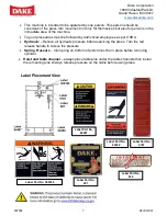
background image


Dake Corporation 


1809 Industrial Park Dr 


Grand Haven, MI 49417 

www.dakecorp.com


907002 


REV012021 


SET UP 


For shipping convenience, the gauge, pump handle, hoist crank, screw nose and base angles 

were removed from the press. Assemble these parts to the press in the following order: 

1.  Bolt the base angles to the uprights using the four bolts and nuts furnished. Shoulder the 

base angles against the stops on the uprights. 

2.  The press should be set on a level floor with the base angles touching the floor at all 

points, using shims where necessary. Then secure the base angles to the floor using 

four, 1/2” bolts included.  

3.  Install the pressure gauge using the hydraulic sealant to ensure a sealed fit. 
4.  Insert the pump handle into the handle socket and fasten in place by means of the set 

screw on top of the handle socket. 

5. 

CAUTION!


 Place the hoist crank on to the lift drum shaft. Remove the table pins and 

turn the crank to get the table to a desired height. Check to make sure the hoist cable is 

tracking correctly. Run the table channels from top to bottom, the cable should be on 

each of the two upper pulleys and should track back and forth on the cable drum.  

b.  If a tracking problem exists, contact the Dake factory for instructions.  

6.  Fasten nosepiece to the end of the screw using the thumbscrew included. 


FILLING PRESS WITH OIL 


Recommended to replace hydraulic oil every 6 months of machine use. 


IMPORTANT!

 ONLY FILL WITH NEW, CLEAN, LIGHT HYDRAULIC OIL. UNDER NO 

CIRCUMSTANCES USE DIRTY OIL. 

1.  Use Mobil DTE 24 or equivalent. 
2.  Filter the oil to remove any possible dirt. 
3.  Put the piston in to its maximum upper position. 
4.  Fill the reservoir with 3 quarts of oil. 
5.  Remove the screw plug from the gauge extension on the top of the work head. 
6.  Close the release valve handwheel and pump oil into the work head until oil is visible in 

the standpipe. 

a.  This will remove all air from the chamber above the piston. 

If oil leaks by the piston, the reservoir should be drained and refilled with the piston in the 

maximum upper position. 

Summary of Contents for 50H

Page 1: ...3253 Grand Haven MI 49417 DAKE HAND OPERATED HYDRAULIC PRESS Model 50H INSTRUCTIONAL MANUAL Read and understand all instructions and responsibilities before operating Failure to follow safety instruct...

Page 2: ...ED WARRANTY 2 RETURN REFUND POLICY 4 SAFEGUARDING THE POINT OF OPERATION 5 SPECIFICATIONS 6 SAFETY 6 SET UP 8 FILLING PRESS WITH OIL 8 OPERATION 9 CONTROLS 9 MAINTENANCE 9 LUBRICATION 9 TROUBLESHOOTIN...

Page 3: ...o the repair work completed The standard limited warranty includes repair of the defective component part at no cost to the end user Warranty Process Subject to the conditions hereinafter set forth th...

Page 4: ...stallation or failure to operate or maintain the unit in accordance with the printed instructions provided c Defects or malfunctions resulting from abuse accident neglect or damage outside of prepaid...

Page 5: ...ved by Customer Service a representative will supply a Return Material Authorization RMA number The returned item must have the provided RMA number clearly marked on the outside packaging Any item rec...

Page 6: ...ration safeguarding system The standard also discusses additional responsibilities of the employer Some of the key responsibilities are The employer is responsible for the safety use and care of the h...

Page 7: ...this information must be provided to assist in identifying the specific machine SAFETY Employer is responsible to perform a hazard PPE assessment before work activity Follow recommended precautions an...

Page 8: ...orized employees as per OSHA Hydraulic Relieve all hydraulic pressure before servicing the press Turn the red release handle to relieve the pressure Spring Pressure Clamp ring on bottom of piston must...

Page 9: ...crank to get the table to a desired height Check to make sure the hoist cable is tracking correctly Run the table channels from top to bottom the cable should be on each of the two upper pulleys and s...

Page 10: ...ed position Always keep the valve firmly closed when operating the press until you want to release the pressure Screw Handwheel Part No 716519 raises or lowers the ram screw in and out of the piston a...

Page 11: ...and drain all oil out of the reservoir 2 Remove parts pipe plug Part No 588 check valve spring Part No 579 and ball valve Part No 586 then clean out the port hole and valve seat thoroughly 3 Using a s...

Page 12: ...586 4 Piston Packing is worn or damaged Part No 573 5 Gauge is defective Part No 71266 1 Replace Pump Plunger leather 2 Remove and clean Check Balls and Seats 3 Reseal Ball on Seat 4 Replace Piston P...

Page 13: ...0 x 1 2 Nylock 28297 1 14 Handle Socket Pin 594 3 15 Valve Rod 1129 1 4 Washer 12 Flat 43629 1 16 Valve Rod Packing Nut 576 1 5 Pump Plunger Leather 599 1 17 Valve Rod Packing 987 8 6 Check Valve Spri...

Page 14: ...NPTF 596 1 31 Ram Spring 556 1 32 Piston Assembly Serial No 192522 701801 1 33 Piston Assembly Serial No 192523 716222 1 34 Piston Leather Serial No 192522 557 1 Packing Ring Serial No 192523 17878 3...

Page 15: ...w Adjusting Wheel 716521 1 56 Pulley 602 2 37 Yoke 593 1 Pulley Bolt 43342 2 39 Gauge 71266 1 Hex Nut 3 8 16 43912 2 Bushing 81384 1 57 Vent Tube 67761 1 40 Gauge Extension 731 1 58 1 8 NPT Fitting 71...

Page 16: ...x 1 1 4 43348 4 49 Table Channel 701091 2 50 Frame only 700116 1 F9 Lock Washer 1 2 43647 4 51 Base Angle 566 2 F10 Hex Nut 1 2 13 43916 8 52 3 8 NPT 37 Fitting 1251 2 F11 Socket Cap Screw 1 2 14 x 2...

Page 17: ...y 737 1 64 Worm Shaft 384 1 73 Worm Gear 736 1 65 Retaining Ring 27437 2 74 Cable Drum 723 1 66 Worm Key 47364 1 75 Retaining Ring 43992 1 67 Worm 385 1 Complete Table Hoist Assembly 700112 S 68 Hoist...

Reviews: