background image

Removing Collected Water

1. In Cool, Dry or Heat mode operating, the condensation water will be drained to

■ Drainage way as follows.

the chassis.

2. When the chassis is full with water, the buzzer will give out 8 sounds and "H8" is 

   displayed to remind user to discharge water:

    ● Move the unit to a suitable place for discharging water; do not tilt the unit and 

       keep it horizontal during moving;

    ● Take the drainage pipe from the clip and pull out the rubber plug on the 

       drainage pipe to discharge water;

    ● After full water protection is eliminated and the compressor has been stopped 

       for 3 minutes, the unit will resume operation.

2

2

Summary of Contents for PORTABLE Series

Page 1: ...INSTALLATION AND MAINTENANCE MANUAL Serie PORTABLE Edition R00 Models ADP 12FX A3 ADP 12F CX A3...

Page 2: ...roughout the EU To prevent possible harm to the environment or human health from un controlled waste disposal recycle it responsibly to promote the sustainable reuse of mate rial resources To return y...

Page 3: ...components that produced by other manufacturers 6 After verification the problem or dispute is caused by the quality specification or majeure 7 The damage is caused by natural calamities bad using en...

Page 4: ...e appliance read the service manual first Appliance filled with flammable gas R290 Appliance shall be installed operated and stored in a room with a floor area larger The appliance shall be stored in...

Page 5: ...nto the air conditioner Do not repair or disassemble the air conditioner by yourself Do not put or hang dripping objects above the air conditioner Keep children from playing or climbing on the air con...

Page 6: ...onment During operation close doors and windows to improve cooling effect Please keep air inlet and air outlet clean no obstacles to avoid noise and vibration Please put the air conditioner at smooth...

Page 7: ...4 Castor 5 Plug of power cord Wire fixing hook 7 Filter 8 Air inlet 9 Joint A 10 Heat discharge pipe 11 Joint B C 12 Remote controller hook 6 Part s Name Installation accessories can t be discarded N...

Page 8: ...er will give out a sound Meanwhile corresponding indicator on control panel will be bright Under OFF status dual 8 nixie tube on control panel won t display Under ON status dual 8 nixie tube on contro...

Page 9: ...eed will circulate as low speed medium speed high speed auto fan low speed Fan button 4 Timer 5 Press timer button to enter into timer setting mode Under this mode press or button to adjust the timer...

Page 10: ...tion time Condensation may form on the louvers Do not adjust the horizontal louvers to the lowest or the highest position in the 2 Left right air flow direction Hold the vertical louver as shown in th...

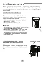
Page 11: ...gnal Make sure nothing such as curtains blocks the The signal effective distance is 8m Do not expose the receiver window to direct sunlight Use of certain fluorescent lamp in the same room Do not leav...

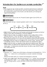
Page 12: ...de Cool mode Dry mode Fan mode Heat mode TIMER ON TIMER OFF 1 On Off button 2 Mode button button 4 Swing button 5 Fan button 6 Sleep button 7 Timer button 8 Health button 9 WiFi button Light function...

Page 13: ...Heat Under this mode air conditioner operates under heating mode Press Fan Speed button can adjust the fan speed Cooling only unit won t receive heating mode signal If setting heat mode with remote co...

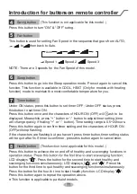
Page 14: ...ess button or button to adjust timer setting time will change quickly if holding or button Time setting range is 0 5 24hours Press this button again to confirm timer setting and the characters of HOUR...

Page 15: ...ns simultaneously to set the lamp on or off and send the code After being energized the lamp is defaulted on 1 Press the back side of remote controller marked the cover of battery box along the arrow...

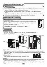
Page 16: ...dust on the surface of outer case please use soft towel to wipe it If the outer case is very dirty such as grease please use neutral abluent to wipe it a Press the clasp as shown in the fig and then...

Page 17: ...t and sundries on the air conditioner 4 Eliminate accumulated water in chassis refer to the section of Drainage way for details 5 Check whether window bracket is damaged or not If yes please contact d...

Page 18: ...losed Is plug loose Whether the air switch is trip ped off or fuse is burnt Is there s malfunction for the circuit Whether the unit is restarted up after stopping immediately Wait after power recovery...

Page 19: ...cold air air conditioner will delay for a while to be started up which is the normal phenomenon It s the normal phenomenon Air conditioner is defrosting will resume operation There s off the room such...

Page 20: ...in the unit ERROR CODE and high humidity environment if ambient temperature is too high power off the unit and then energize it for operation after the ambient temperature drops to 35 below blocked by...

Page 21: ...y Safety precaution 1 Must follow the electric safety regulations when installing the unit 2 According to the local safety regulations use qualified power supply circuit 3 For appliances with type Y a...

Page 22: ...in connector heat discharge pipe Optional Window kit Bracket Rain guard Insect guard net Window panel Exhaust cover Adjustment panel Extension panel screw remote control pipe hoop pipe clip rubber plu...

Page 23: ...re Hook Assemble the wire hook at the back of the unit with screws the direction of wire Wind the power cord around the wire hook direction of wire hook is upward direction of wire hook is downward sc...

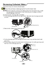
Page 24: ...t NOTICE When using the continuous drainage option from the bottom hole install drainage pipe as follow before using otherwise poor drainage will affect normal operation of the unit There are 2 ways t...

Page 25: ...ounds and H8 is displayed to remind user to discharge water Move the unit to a suitable place for discharging water do not tilt the unit and keep it horizontal during moving Take the drainage pipe fro...

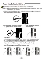
Page 26: ...hole place portable on a level surface and make sure garden hose is clear of any obstructions and is directed downward Placing portable on an uneven surface or improper hose installation may result i...

Page 27: ...guards to the insect guard net Insert all three projections on each rain guard into the holes in the insect guard net 2 Attach the guard combined above to the window panel Push the insect guard net fi...

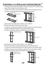
Page 28: ...1 Open the window sash and place the window panel on the window sill 2 Slide the adjustment panel to fit the window frame width 3 Secure the window panel to the sill with screws Inner width of the win...

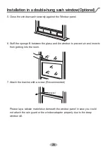
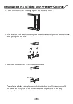
Page 29: ...e the window sash securely against the Window panel 7 Attach the bracket with a screw Recommended Please lay a tabular material underneath the window panel in case you could not attach the rain guard...

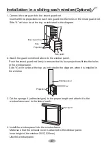
Page 30: ...sect guard net Insert all three projections on each rain guard into the holes in the insect guard net 2 Attach the guard combined above to the window panel Push the insect guard net firmly to ensure t...

Page 31: ...he window frame 2 Slide the adjustment panel to fit the window frame height 3 Secure the window panel to the window frame with screws Inner height of the window 38 5 980mm 59 1500mm Use the window pan...

Page 32: ...a tabular material underneath the window panel in case you could not attach the rain guard or the window adapter properly due to the deep window sill Bracket Installation in a sliding sash window Opt...

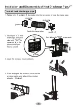
Page 33: ...harge pipe clockwise clockwise joint A joint B C heat discharge pipe 2 Insert joint A of heat discharge pipe the side with TOP is upwards into the groove until you hear a sound 3 Lead the exhaust hose...

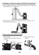
Page 34: ...arge pipe correct correct correct wrong The length of the heat discharge pipe is less than 1m It is recommended to use it with shortest length the pipe or connect it with other When installing heat di...

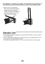
Page 35: ...t discharge pipe 2 Remove joint B C from 1 Remove joint A Press the clasp and lift joint A upwards to outdoors remove it upwards clasp disassemble joint A would easily cause malfunction Installation a...

Page 36: ...nstallation and Disassembly of Heat Discharge Pipe 33 PUSH PUSH Operation Test Put through the power supply and then press ON OFF button on remote contro ller to start the unit Press mode button to se...

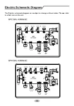
Page 37: ...K SA The Electric schematic diagram are subject to change without notice Please refer to which one on the unit Electric Schematic Diagram 34 R M OUTTUBE RT3 TUBE RT2 RT1 BOARD DISPLAY REC RECEIVER BOA...

Page 38: ...potentially toxic or flammable atmospheres Ensure that the leak detection equipment being used is suitable for use with all applicable refrigerants i e non sparking adequately sealed or intrinsically...

Page 39: ...all include initial safety checks and component inspection procedures If a fault exists that could compromise safety then no electrical supply shall be connected to the circuit until it is satisfactor...

Page 40: ...inguished remove refrigerant purge the circuit with inert gas evacuate purge again with inert gas open the circuit by cutting or brazing If a leakage of refrigerant is found which requires brazing all...

Page 41: ...mpletion of charging but prior to commissioning A follow up leak test shall be carried out prior to leaving the site Ensure that contamination of different refrigerants does not occur when using charg...

Page 42: ...order Empty recovery cylinders are evacuated and if possible cooled before recovery occurs The recovery equipment shall be in good working order with a set of instructions concerning the equipment tha...

Page 43: ...Eurofred S A Marqu s de Sentmenat 97 08029 Barcelona www eurofred es...

Reviews: