


[8]
Rev 4/15/14
Dairy Tech, Inc.
Service Manual:
DT10G, DT30G &DT60G
Installation:
Preparing the Machine
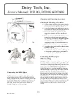
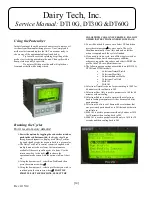
Unpacking the DT60G
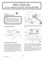
Mounting the Control Panel
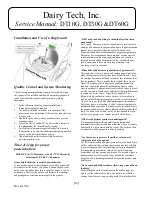
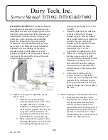
The pasteurizing unit is typically shipped with the control box
detached and packed in the tank of the unit. Mounting of the
control box will be required. Gently remove the controller from
the milk pot. Four mounting holes are provided on the top
surface of the unit. Using the bolts that are provided, attach the
control unit in an upright fashion to the top lid of the
pasteurizer. The screw slots may allow some adjustment of the
propeller and shaft if required later. The electrical connections
are already made. Use care to not stretch these connections. See
the next figure for the DT10G and DT30G.
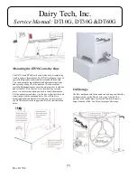
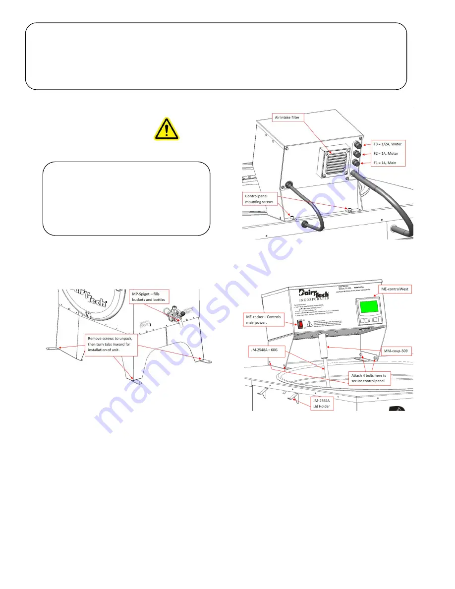
Here is another image shown below of the DT60G which has
side mounting screws to secure the control box to the top of the
cabinet.
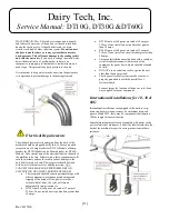
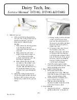
The motor shaft must also be attached by inserting it through
the side entry of the coupler, followed by right-hand threading
of the shaft into the coupler. The shaft can be gripped at the
knurling located midway on the shaft. Only finger tighten as
shown in the next image.
Dairy Tech recommends that the stirring shaft be removed from
the coupler any time the pasteurizer is being moved. This will
help to avoid a bend in the shaft. A bent shaft can result in
premature failure of the drive motor. Treat the shaft with due
care any time it is not in the machine.
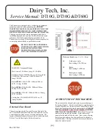
Warning:
Install the unit according to the installation
instructions. To reduce the risk of fire, electric shock,
serious injury or death to persons, read the important
safety instructions before operating this Pasteurizer.
Before using this unit for the first time, wash out the
inside of the drum with hot soapy water and rinse
clean.
Summary of Contents for Platinum Series
Page 2: ...2 Rev 4 15 14 Dairy Tech Inc Service Manual DT10G DT30G DT60G...
Page 31: ...31 Rev 4 15 14 Schematic for Model DT10 30 60G 200 to 240VAC 1P 50 60Hz USA Domestic...
Page 32: ...32 Rev 4 15 14 Schematic for Model DT10 30 60G 200 to 240VAC 1P 50 60Hz England Japan...
Page 33: ...33 Rev 4 15 14 Schematic for Model DT10 30 60G 400VAC 3P Europe...
Page 34: ...34 Rev 4 15 14 NOTES...
Page 38: ...38 Rev 4 15 14...