background image

19 Troubleshooting

Installation and operation manual

41

RXYQQ8~20U7Y1B
VRV IV Q+ series heat pump
4P546221-1B – 2020.10

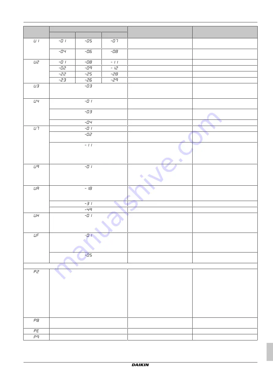
Main code

Sub code

Cause

Solution

Master

Slave 1

Slave 2

Reversed power supply phase
malfunction

Correct phase order.

Reversed power supply phase
malfunction

Correct phase order.

INV1 voltage power shortage

Check if power supply is within range.

INV1 power phase loss

Check if power supply is within range.

INV2 voltage power shortage

Check if power supply is within range

INV2 power phase loss

Check if power supply is within range.

Malfunction code: System test run not
yet executed (system operation not
possible)

Execute system test run.

Faulty wiring to Q1/Q2 or indoor -
outdoor

Check (Q1/Q2) wiring.

Faulty wiring to Q1/Q2 or indoor -
outdoor

Check (Q1/Q2) wiring.

System test run abnormal ending

Execute test run again.

Warning: faulty wiring to Q1/Q2

Check Q1/Q2 wiring.

Malfunction code: faulty wiring to Q1/
Q2

Check Q1/Q2 wiring.

▪ Too 

many 

indoor 

units 

are

connected to F1/F2 line

▪ Bad  wiring  between  outdoor  and

indoor units

Check indoor unit amount and total
capacity connected.

System mismatch. Wrong type of
indoor units combined (R410A,
R407C, RA, Hydrobox, etc)

Indoor unit malfunction

Check if other indoor units have
malfunction and confirm indoor unit
mix is allowed.

Connection malfunction over indoor
units or type mismatch (R410A,
R407C, RA, Hydrobox, etc)

Check if other indoor units have
malfunction and confirm indoor unit
mix is allowed.

Wrong unit combination (multi system) Check if unit types are compatible.

Wrong unit combination (multi system) Check if unit types are compatible.

Auto address malfunction
(inconsistency)

Check if transmission wired unit
amount matches with powered unit
amount (by monitor mode) or wait till
initialisation is finished.

Auto address malfunction
(inconsistency)

Check if transmission wired unit
amount matches with powered unit
amount (by monitor mode) or wait till
initialisation is finished.

Stop valve closed or wrong (during
system test run)

Open stop valves.

Auto charging related

Unusual low pressure on suction line

Close valve A immediately. Push BS1
to reset. Check following items before
retrying autocharge procedure:

▪ Check  if  the  gas  side  stop  valve  is

opened correctly.

▪ Check  if  the  valve  of  the  refrigerant

cylinder is opened.

▪ Check if the air inlet and outlet of the

indoor unit are not obstructed.

Freeze-up prevention indoor unit

Close valve A immediately. Push BS1
to reset. Retry autocharge procedure.

Automatic charging nearly finished

Prepare for autocharge stopping.

Automatic charging finished

Finish autocharge mode.

Summary of Contents for VRV IV Q+ Series

Page 1: ...ion and operation manual VRV IV Q series heat pump English Installation and operation manual VRV IV Q series heat pump RXYQQ8U7Y1B RXYQQ10U7Y1B RXYQQ12U7Y1B RXYQQ14U7Y1B RXYQQ16U7Y1B RXYQQ18U7Y1B RXYQ...

Page 2: ...iejszymi poprawkami 18 19 20 21 22 23 24 25 Directivelor cu amendamentele respective Direktive z vsemi spremembami Direktiivid koos muudatustega Direktyvose su papildymais Direkt v s un to papildin ju...

Page 3: ...staava kyll stysl mp tila M C Kylm aine N Varmuuspainelaitteen asetus P bar Valmistusnumero ja valmistusvuosi katso mallin nimikilpi Maxim ln p pustn tlak PS K bar Minim ln maxim ln p pustn teplota TS...

Page 4: ...8 2 15 Symptom The display shows 88 14 8 2 16 Symptom The compressor in the outdoor unit does not stop after a short heating operation 14 8 2 17 Symptom The inside of an outdoor unit is warm even whe...

Page 5: ...tion manual Installation and operation instructions Format Paper in the box of the outdoor unit Installer and user reference guide Preparation of the installation reference data Detailed step by step...

Page 6: ...NOT use taped wires stranded conductor wires extension cords or connections from a star system They can cause overheating electrical shock or fire Do NOT install a phase advancing capacitor because t...

Page 7: ...of other parts must be done by an authorized installer and must comply with applicable legislation Units must be treated at a specialized treatment facility for reuse recycling and recovery By ensurin...

Page 8: ...e WARNING Do NOT modify disassemble remove reinstall or repair the unit yourself as incorrect dismantling or installation may cause an electric shock or fire Contact your dealer In case of accidental...

Page 9: ...range is only valid in case direct expansion indoor units are connected to the VRV IV system 6 2 Operating the system 6 2 1 About operating the system Operation procedure varies according to the combi...

Page 10: ...al of the user interface 6 3 Using the dry program 6 3 1 About the dry program The function of this program is to decrease the humidity in your room with minimal temperature decrease minimal room cool...

Page 11: ...operating in the horizontal direction It may cause dew or dust to settle on the ceiling or flap 6 5 Setting the master user interface 6 5 1 About setting the master user interface c c b b a a VRV rep...

Page 12: ...from fan heaters gas cookers etc is present Always have qualified service personnel confirm that the point of leakage has been repaired or corrected before resuming operation 8 Troubleshooting If one...

Page 13: ...anger gas temperature sensor malfunction outdoor Suction temperature sensor malfunction outdoor De icing temperature sensor malfunction outdoor Liquid temperature sensor after subcool HE malfunction o...

Page 14: ...s because the user interface is intercepting noise from electric appliances other than the air conditioner The noise prevents communication between the units causing them to stop Operation automatical...

Page 15: ...ESULT OF LEAK CHECK OPERATION REQUEST FOR THE INDICATION OF ADDITIONAL REFRIGERANT CHARGING AND LEAK DETECTION OPERATION RESULT BE SURE TO FILL OUT THE BLANKS WHICH ARE NEEDED FOR AFTER SALE SERVICES...

Page 16: ...15 C a e c d d c b a VRV IV replacement heat pump outdoor unit b Refrigerant piping c VRV direct expansion DX indoor unit d User interface dedicated depending on indoor unit type e Cool Heat changeov...

Page 17: ...a b c d e a Electrical component box cover b Front side c Power supply terminal block d Sealing material e Moisture and dirt could enter NOT allowed Allowed 13 3 Mounting the outdoor unit 13 3 1 To p...

Page 18: ...and thickness and if the pipes and branch piping are not corroded If the existing field piping does not comply with the above conditions replace the existing field piping with field piping that meets...

Page 19: ...34 9 1 0 38 1 41 3 1 1 a If annealed temper grade is 1 The refrigerant pipes and branches must meet the condition of design pressure 33 bar 3 3 MPa If it is NOT possible to confirm this use the refrig...

Page 20: ...If the piping length between the outdoor units exceeds 2 m create a rise of 200 mm or more in the gas line within a length of 2 m from the kit If Then 2 m a b 2 m 2 m a 2 m 2 m 200 mm 200 mm b 2 m 2 m...

Page 21: ...allowed Allowed Make sure that the total length of the piping connected to the joint is absolute straight for more than 500 mm Only if a straight field piping of more than 120 mm is connected more tha...

Page 22: ...lve size mm Tightening torque N m when opening or closing Valve body Hexagonal wrench Service port 9 5 5 7 4 mm 10 7 14 7 12 7 8 10 15 9 14 16 6 mm 19 1 19 21 8 mm 25 4 14 2 7 To remove the spun pipes...

Page 23: ...ant piping involves Checking for any leakages in the refrigerant piping Performing vacuum drying to remove all moisture air or nitrogen in the refrigerant piping If there is a possibility of moisture...

Page 24: ...our 3 Should you fail to reach the target vacuum within 2 hours or maintain the vacuum for 1 hour the system may contain too much moisture In that case break the vacuum by pressurising with nitrogen g...

Page 25: ...or manual charging This step is included in below procedure see To charge refrigerant 428 It can be skipped but charging will take longer then A flow chart is available which gives an overview of the...

Page 26: ...kg 12 HP N 6 C2 0 kg C C1 C2 0 5 kg Metric piping When using metric piping replace the weight factors in the formula by the ones from the following table Inch piping Metric piping Piping Weight facto...

Page 27: ...t on the additional refrigerant charge label Go to test run Step 4b Close valve B R Q R Q R Q Step 5 Connect valve A to refrigerant charge port Open all outdoor unit stop valves Proceed with automatic...

Page 28: ...al refrigerant charge label Go to test run Following codes appear e 2 indoor temperature out of range and e 3 outdoor temperature out of range Push BS1 to leave program Charging is finished Fill in th...

Page 29: ...6 Step 6a To automatically charge refrigerant INFORMATION The automatic refrigerant charging has limits as described below Out of these limits the system cannot operate the automatic refrigerant charg...

Page 30: ...tial NOTICE Applicable legislation on fluorinated greenhouse gases requires that the refrigerant charge of the unit is indicated both in weight and CO2 equivalent Formula to calculate the quantity in...

Page 31: ...nd select the next higher recommended fuse capacity Example Combining the RXYQQ30 by using the RXYQQ18 and RXYQQ12 Minimum circuit ampacity of the RXYQQ18 35 0 A Minimum circuit ampacity of the RXYQQ1...

Page 32: ...or unit e Outdoor unit In case of multi outdoor unit installation F1 F2 F1 F2 Q1 Q2 Q1 Q2 A1P d d e f b a c Q1 Q2 a Unit A master outdoor unit b Unit B slave outdoor unit c Unit C slave outdoor unit d...

Page 33: ...Power supply terminal block f Connect each power wire RED to L1 WHT to L2 BLK to L3 and BLU to N g Earth wire GRN YLW h Tie wrap i Cup washer j When connecting the earth wire it is recommended to perf...

Page 34: ...he current field setting value and changing the current field setting value is possible In general normal operation can be resumed without special intervention after changing field settings Some field...

Page 35: ...nit What How Changing and accessing the setting in mode 1 Once mode 1 is selected push BS1 one time you can select the wanted setting It is done by pushing BS2 Accessing the selected setting s value i...

Page 36: ...et C 0 default Auto 2 6 3 7 4 8 5 9 6 10 7 11 2 9 Tc target temperature during heating operation 2 9 Tc target C 0 default Auto 1 41 3 43 6 46 2 20 Manual additional refrigerant charge 2 20 Descriptio...

Page 37: ...ce of 2 M or more is attained by applying a voltage of 500 V DC between power terminals and earth NEVER use the megatester for the transmission wiring Fuses circuit breakers or protection devices Chec...

Page 38: ...egment display idle Abnormal completion Indication of malfunction code on the 7 segment display Refer to 17 5 Correcting after abnormal completion of the test run 438 to take actions for correcting th...

Page 39: ...rface s display or transmission wiring between the outdoor unit and the indoor unit Electronic expansion valve malfunction main Y1E A1P X21A Check connection on PCB or actuator Electronic expansion va...

Page 40: ...tuator De icing temperature sensor malfunction R7T A1P X30A Check connection on PCB or actuator Liquid temperature sensor after subcool HE malfunction R5T A1P X30A Check connection on PCB or actuator...

Page 41: ...alfunction Check if other indoor units have malfunction and confirm indoor unit mix is allowed Connection malfunction over indoor units or type mismatch R410A R407C RA Hydrobox etc Check if other indo...

Page 42: ...d 500 mm e 20 mm a 50 mm b 100 mm c 50 mm d 500 mm e 100 mm Layout A B C D A B Possibility 1 Possibility 2 5 a 10 mm b 500 mm c 10 mm d 500 mm e 20 mm f 900 mm a 50 mm b 500 mm c 50 mm d 500 mm e 100...

Page 43: ...ed are listed below INFORMATION The wiring diagram on the outdoor unit is only for the outdoor unit For the indoor unit or optional electrical components refer to the wiring diagram of the indoor unit...

Page 44: ...ion valve liquid cooling Y1S Solenoid valve main Y2S Solenoid valve accumulator oil return Y3S Solenoid valve oil 1 Z C Noise filter ferrite core Z F A2P A5P Noise filter with surge absorber Connector...

Page 45: ...expansion valve main Y2E Electronic expansion valve sub cool Y3E Electronic expansion valve liquid cooling Y1S Solenoid valve main Y2S Solenoid valve accumulator oil return Y3S Solenoid valve oil 1 Y4...

Page 46: ......

Page 47: ......

Page 48: ...4P546221 1B 2020 10 Copyright 2018 Daikin 4P546221 1 B 0000000Y Verantwortung f r Energie und Umwelt...

Reviews: