background image

IM 1227 • MODELS DC THERMOSTATS 24 www.DaikinApplied.com

7-D

ay

 P

rogrammable

 C

ommerCial

 D

igiTal

 T

hermosTaTs

Heating and Cooling System Runtime— 

Energy Watch 

(Setup Steps 8–10) 

Current Heat Runtime Hours (Setup Step 8)

 – This counter 

keeps track of the number of hours the system has run in 

Heating. Press OUTDOOR to reset. 

Current Aux Strip Heat Runtime Hours (Setup Step 9)

 – This 

counter keeps track of the number of hours the system has run 

in Auxiliary Heating. This setup step is only available when the 

thermostat jumpers are configured for Heat Pump and Electric 

Heat. Press OUTDOOR to reset. 

Current Cool Runtime Hours (Setup Step 10)

 – This counter 

displays the number of hours the system has run in Cooling. 

Press OUTDOOR to reset. 

Current Override Hours (Setup Step 11)

 – This counter 

displays the number of hours the system has run in Override. 

Press OUTDOOR to reset.

UV Lamp Runtime 

(Setup Steps 12, 16) 

Current UV Lamp Calendar Days (Setup Step 12)

 – number 

of calendar days that have elapsed to help the user track UV 

lamp runtime. Press OUTDOOR to reset. 

Set UV Lamp Calendar Days (Setup Step 16)

 – This timer 

allows the user to specify the number of calendar days the UV 

Lamp will operate before the “Replace UV Lamp” alert will be 

displayed. Press DOWN continuously until OFF appears to 

disable this alert. 

Humidifier Runtime 

(Setup Steps 13, 17) 

Current Humidifier Calendar Days (Setup Step 13)

 – This 

counter displays the total number of calendar days that have 

elapsed to help the user track the Humidifier runtime. Press 

OUTDOOR to reset. 

Set Humidifier Calendar Days (Setup Step 17)

 – This timer 

allows the user to specify the number of calendar days the 

Humidifier will run before the “Service Humidifier” alert will be 

displayed. Press DOWN continuously until OFF appears to 

disable this alert.

Time Period Programming    

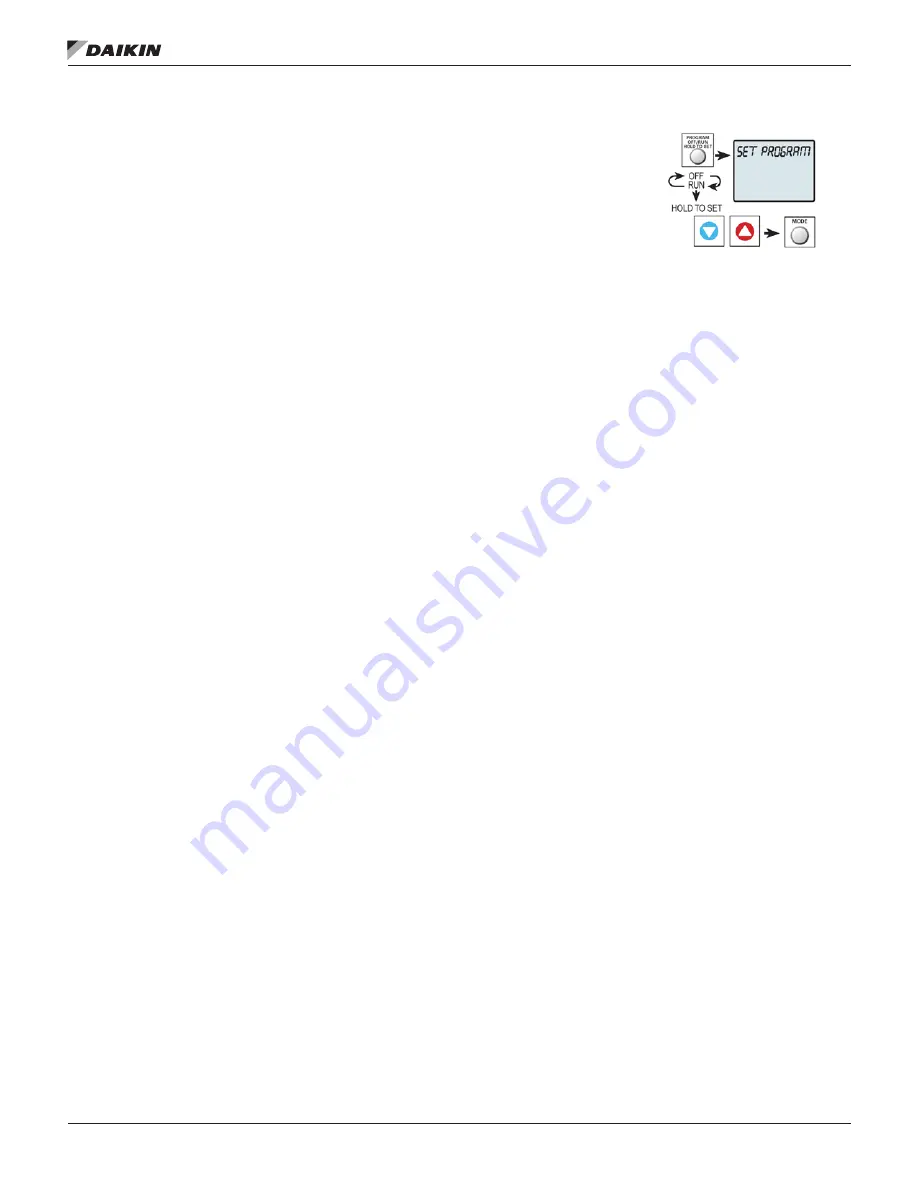
To enter Time Period 

Programming screens, Press 

and hold PROGRAM until the 

scrolling prompt appears. 

OFF

 – Time Period Program 

is off. 

RUN

 – Time Period Program 

is running. 

HOLD TO SET

 – Press and hold PROGRAM to make Time 

Period Programming changes. 

Programming a Daily Schedule 

Select number of Occupied time periods

 – Press the UP or 

DOWN buttons to choose the maximum number of Occupied 

time periods to program. (1-3) Press MODE to advance to the 

next step. 

Select Occupied 1 Cool Setpoint 

– Press the UP or DOWN 

buttons to adjust the cool setpoint desired. Press MODE to 

advance to the next step. 

Select Occupied 1 Heat Setpoint

 – Press the UP or DOWN 

buttons to adjust the heat setpoint desired. Press MODE to 

advance to the next step. 

Select Unoccupied Cool Setpoint

 – Press the UP or DOWN 

buttons to adjust the cool setpoint desired. Press MODE to 

advance to the next step. 

Select Unoccupied Heat Setpoint

 – Press the UP or DOWN 

buttons to adjust the heat setpoint desired. Press MODE to 

advance to the next step. 

Select Day of Week to program

 – Press the UP or DOWN 

buttons to choose the day of the week to be programmed. 

Press MODE to advance to the next step. 

Select Occupied 1 Start Time

 – Press the UP or DOWN 

buttons to adjust the time of day desired. Press MODE to 

advance to the next step. 

Select Occupied 1 Stop Time

 – Press the UP or DOWN 

buttons to adjust the time of day desired. Press MODE to 

advance to the next step. 

Select Occupied 1 Enable

 – Press the UP or DOWN buttons to 

choose to enable the program to run on that day. Press MODE 

to advance to the next step. 

Copy Current Day to Next

 – Press the UP button to choose to 

Copy the current day to another day. Press the UP or DOWN 

buttons to choose which day to copy to. Press MODE to 

confirm. Continue to Press MODE to copy to more days. Press 

the DOWN button to program another day with a different 

schedule. 

Program Another Day

 – Press the DOWN button to choose to 

program another day with a different schedule. Press MODE. 

Press the UP or DOWN buttons to choose the desired day. 

Press MODE to advance to the next step. 

Press Program Button to exit Time Period Programming 

Summary of Contents for TSTATD4271C

Page 1: ...Resolution Touchscreen Thermostat 7 Day Programmable Thermostat Installation and Maintenance Manual IM 1227 Group Applied Air Systems Part Number IM 1227 Date November 2014 Models DC Digital Thermost...

Page 2: ...nstaller Setup 25 Locking Unlocking the Keypad 25 How to Change Settings in the Setup Screens 25 Auxiliary Output 27 Dry Contact Operation 28 Light Activated Operation 29 Press Outdoor To Clear All Me...

Page 3: ...et the thermostat mode to OFF prior to changing settings in setup or restoring Factory Defaults NOTICE This device complies with Part 15 of the FCC Rules Operation is subject to the following two cond...

Page 4: ...lays the outdoor temperature when selected 6 Outdoor icon indicates the temperature displayed is from the optional outdoor sensor 7 Desired Set Temperature indicates desired room temperature s Also di...

Page 5: ...ust heat and cool setpoints individually choose HEAT mode to adjust the heat setpoint and COOL mode to adjust the cool setpoint then return to AUTO mode Heat or Cool Mode Pressing the UP or DOWN butto...

Page 6: ...h the letter of the terminal for easy reconnection to the new thermostat Keep the old thermostat for reference purposes until your new thermostat is functioning properly Wire Connections If the termin...

Page 7: ...an G terminal in heating When ELEC is chosen the thermostat will energize the fan in heating Sample Wiring Diagrams Table 2 Conventional Heating and Cooling Systems 3 Wire Heat Only Residential Commer...

Page 8: ...ctric Setup Step 26 is set to 2 Number of Compressor Stages Figure 8 Dry Contact and Outdoor Sensor Test Operation This thermostat has a diagnostic feature that enables testing of all outputs This fea...

Page 9: ...screens Language Setup Step 18 Setup step instructions on the scrolling display can be set for English Spanish or French Press the SETUP button then press MODE repeatedly until the Language setupstep...

Page 10: ...every minute a wireless outdoor sensor s temperature reading is updated once every 5 minutes System Runtimes These setup steps allow the user to monitor equipment runtimes and program service alerts...

Page 11: ...oint Press the UP or DOWN buttons to adjust the heat setpoint desired Press MODE to advance to the next step Select Day of Week to program Press the UP or DOWN buttons to choose the day of the week to...

Page 12: ...Setup Step 1 This thermostat may be configured to be programmable or non programmable 7 Day Program Allows all seven days to be programmed independently Non Program No advanced time period programming...

Page 13: ...e number of degrees or minutes that the thermostat waits before it initiates the stages of heating or cooling 1st Stage Deadband Setup Step 27 Specifies the minimum temperature difference between the...

Page 14: ...s closed until the connected device opens the circuit Dry Contact Use Setup Step 71 PAN If PAN is selected when the dry contact is active the thermostat will lockout the compressor terminal s and SERV...

Page 15: ...ermostat mode to OFF prior to changing settings in setup or restoring Factory Defaults NOTICE This device complies with Part 15 of the FCC Rules Operation is subject to the following two conditions 1...

Page 16: ...ays the outdoor temperature when selected 6 Outdoor icon indicates the temperature displayed is from the optional outdoor sensor 7 Desired Set Temperature indicates desired room temperature s Also dis...

Page 17: ...into Occupied 1 settings for 30 minutes Each press of the OVERRIDE button will add another 30 minutes of time for up to 4 hours If the maximum time has been set the next press of the OVERRIDE button w...

Page 18: ...Keep the old thermostat for reference purposes until your new thermostat is functioning properly Wire Connections If the terminal designations on your old thermostat do not match those on the new ther...

Page 19: ...rcial heat pumps this jumper will need to be set for GAS ELEC Consult the commercial heat pump literature When J1 is configured to control a heat pump This jumper J2 must be set to control the appropr...

Page 20: ...t Stage Heat W2 2nd Stage Heat W3 3rd Stage Heat Y1 1st Stage Cool Y2 2nd Stage Cool G Fan J1 Gas Elec J2 O not used J3 Gas Table 6 Heat Pump Systems 5 Wire 1 Stage Cooling 1 Stage Heat Residential Co...

Page 21: ...n on Cooling The scrolling display will read NOTHING ON Next Press UP to turn on and cycle up through the heating stages Press DOWN to turn the heating stages off Press MODE to exit Press DOWN to turn...

Page 22: ...screens Language Setup Step 18 Setup step instructions on the scrolling display can be set for English Spanish or French Press the SETUP button then press MODE repeatedly until the Language setupstep...

Page 23: ...accessory to begin linking process Next press DOWN to enter the wireless linking mode Press MODE to initiate linking Press ACCESSORY to return to the main screen NOTE A wired outdoor sensor s tempera...

Page 24: ...d PROGRAM until the scrolling prompt appears OFF Time Period Program is off RUN Time Period Program is running HOLD TO SET Press and hold PROGRAM to make Time Period Programming changes Programming a...

Page 25: ...Setup Step 1 This thermostat may be configured to be programmable or non programmable 7 Day Program Allows all seven days to be programmed independently Non Program No advanced time period programming...

Page 26: ...ifies the minimum temperature difference between the room temperature and the desired setpoint before the first stage of heating or cooling is allowed to turn on 1 6 degrees For example if the heat se...

Page 27: ...M output when there is no demand to dehumidify Dehumidify Output Normally Closed means voltage is sent to the DEHUM output when there is no demand to dehumidify Fan Off Delay in Seconds Setup Step 55...

Page 28: ...e if a Critical Alarm or Alert error is present Level 2 Aux Output is active if a Critical or Alarm error is present Level 3 Aux Output is active only if a Critical error is present Critical Error Ser...

Page 29: ...s from the display Resetting the Thermostat to the Factory Default Settings for default values see Table 7 on page 31 If for any reason you desire to return all the stored settings back to the factory...

Page 30: ...and testing purposes and is intended for use by a qualified technician See page 14 for more detailed instructions Figure 27 Enter Technician Setup Menu Hold for 5 seconds All icons appear Press MODE...

Page 31: ...10 2 29 3rd Stage Deadband 0 10 2 30 4th Stage Deadband 0 10 2 31 Minutes Between 1st and 2nd Stage 0 60 2 32 Minutes Between 2nd and 3rd Stage 0 60 2 33 Minutes Between 3rd and 4th Stage 0 60 2 34 2n...

Page 32: ...opy Mon to Tues No Yes Occupied 1 Occupied 2 Occupied 3 Wednesday Unoccupied Copy Mon to Tues No Yes Occupied 1 Occupied 2 Occupied 3 Thursday Unoccupied Copy Mon to Tues No Yes Occupied 1 Occupied 2...

Page 33: ...ollowing two conditions 1 this device may not cause harmful interference and 2 this device must accept any interference received including interference that may cause undesired operation These color t...

Page 34: ...IM 1227 MODELS DC THERMOSTATS 34 www DaikinApplied com High Resolution Touch Screen Digital Thermostat Get To Know Your Thermostat Figure 29 Unit Displays...

Page 35: ...he day Figure 30 Dropdown Dashboard Care and Use of Your Thermostat Pencils pens and other sharp objects should never be used on your Color Touch Screen thermostat these may damage your touchscreen On...

Page 36: ...e FAN AUTO fan only runs with a heating or cooling demand NOTE FAN button is disabled during Program Run Mode Figure 34 Fan Selections Override Functions Using the Override Button Unoccupied Operation...

Page 37: ...rvice contact Configure installation settings information and company logo Update thermostat firmware Figure 36 TouchScreen Assistant Display Uploading Photos and Settings to your Thermostat When you...

Page 38: ...ur thermostat including the thermostat s ID Figure 39 Accessory Information Display Setup Upon pressing setup the thermostat will search for available local networks with which to connect After indent...

Page 39: ...h quality background themes to choose from NOTE At 7 PM the background will change to an evening scene and the moon will replace the sun At 7 AM it will return to a daytime scene Custom Wallpaper You...

Page 40: ...Code must be set before Auto Screenlock can be turned on If you forget your passcode enter 6736 for access Use keypad to enter and confirm passcode Figure 41 Keypad Display When the thermostat is loc...

Page 41: ...chScreen screen at night Auto Night Dimmer OFF The screen can be set to dim automatically at night Dimming the display can prolong the life of the backlight Set Idle Brightness 50 Set the screen brigh...

Page 42: ...aver ON Screensaver Setup Screensaver Turn On Delay How long after a button press for the Screensaver to appear 1 3 5 or 30 minutes Screensaver Type Slideshow Digital Clock Analog Clock Change Image A...

Page 43: ...switch settings equipment status runtimes and other settings View Runtime Graphs Track your system s runtime energy usage Last 7 Days Cooling Press the information icon to learn more about each graph...

Page 44: ...e 360 days Service Information Using the Alerts Functions The alerts let you know when your system needs service View Current Alerts View and reset current service alerts here Alerts appear on the bot...

Page 45: ...e OFF Start Schedule Starts On 2nd Day Sun Month March Stop Schedule Ends On 1st Day Sun Month November Setting the Time Press then to scroll down Press NOTE If the Skyport Wi Fi Key is installed on t...

Page 46: ...rch Adjust when Daylight Savings Time ends Stop Schedule Ends On 1st Day Sun Month November Press after making a change to a selection Press or the Home button when finished Schedule Table 17 Schedule...

Page 47: ...Cool Setpoints to desired settings The Time Period May also be Enabled or Disabled Uncheck the enabled box for Time Periods you don t want to use Press DONE when finished When you are finished editin...

Page 48: ...e Repeat button for recurring holidays Pressing a selected holiday will deselect that holiday Figure 47 Selecting a Holiday Using the Repeat Button Choose to repeat the holiday every week month or yea...

Page 49: ...f every month On the last Monday of every month Press SAVE to save your changes and return to Holiday programming Figure 51 Edit Repeating Holiday Display You may now delete all repeating custom holid...

Page 50: ...Auto for fan to run only with heating or cooling Fan Purge OFF Press to turn on Preoccupancy Fan Purge This feature allows the fan to run for a preset amount of time before Occupied 1 begins Preoccupa...

Page 51: ...gs in the Installation Settings menu Humidification Settings Humidify setpoint 0 Adjust Humidify setpoint 0 60 Humidify only with heat OFF When this step is ON Humidify will only run with a demand for...

Page 52: ...ancais Smart Recovery ON OFF Continued Installation Settings Heat Cool Stages Heat Cool Stages Compressor Stages Aux Heat Stages Timers Deadbands Cycles Per Hour Min Heat Cool Difference Compressor Mi...

Page 53: ...3 Hum Dehum Aux Output Polarity Normally Open Normally Closed Sensor Settings Control Sensor Thermostat Sensor Only Wired Sensor Only Average Wired Thermostat Wired Sensor Use Use as Outdoor Sensor Us...

Page 54: ...at before the Occupied start time to bring the room temperature to the Occupied setpoint at the start of the Occupied time period Please allow 4 8 days for Smart Recovery time to adjust When used with...

Page 55: ...Heat Lockout Aux Heat Lockout Temp 65 Aux Heat will not run above this temp 0 75 F GAS EL or HP dip switch must be set for HP and GAS or ELEC dip switch must be set for ELEC For TSTATD4272CGT Models O...

Page 56: ...TouchScreen Assistant to add Dealer s logo See Page 45 Figure 55 Dealer Information Display Upgrade Firmware Press to upgrade the thermostat firmware The SD Card must be in the thermostat SD Card read...

Page 57: ...the terminal for easy reconnection to the new thermostat Keep the old thermostat for reference purposes until your new thermostat is functioning properly Wire Connections If the terminal designations...

Page 58: ...ly return sensor connections IMPORTANT This thermostat requires both R 24 VAC Return and C 24 VAC Common be connected to the backplate terminals TSTATD4272CGT Models Figure 57 TSTATD4271CGT Backplate...

Page 59: ...anything other than a heat pump leave this switch set for GAS EL For some commercial heat pumps this switch may need to be set for GAS EL Consult the commercial heat pump literature O B or O B When th...

Page 60: ...t Residential Commercial 2 Stage Cooling with 3 stage Gas Heat R 24VAC Power C 24VAC Common W1 O B 1st Stage Heat W2 2nd Stage Heat W3 AUX 3rd Stage Heat Y1 1st Stage Cool Y2 2nd Stage Cool G Fan GAS...

Page 61: ...am Mode Setup 1 to 1 5 2 or 7 Day See Selecting Your Program Mode page 20 Troubleshooting Touchscreens Symptom The thermostat touchscreen buttons are not responsive Cause The touchscreen is out of cal...

Page 62: ...e between the heat setpoint and the cool setpoint Heat Setpoint The coolest temperature that the space should drop to before heating is turned on without regard to deadband Icon The word or symbol tha...

Page 63: ...ENLARGED OR CHANGED BY ANY DISTRIBUTOR DEALER OR OTHER PERSON WHATSOEVER ALL WORK UNDER THE TERMS OF THIS WARRANTY SHALL BE PERFORMED DURING NORMAL WORKING HOURS ALL REPLACEMENT PARTS WHETHER NEW OR R...

Page 64: ...GED OR CHANGED BY ANY DISTRIBUTOR DEALER OR OTHER PERSON WHATSOEVER ALL WORK UNDER THE TERMS OF THIS WARRANTY SHALL BE PERFORMED DURING NORMAL WORKING HOURS ALL REPLACEMENT PARTS WHETHER NEW OR REMANU...

Page 65: ......

Page 66: ...t to its standard terms and conditions of sale including Limited Product Warranty Consult your local Daikin Applied representative for warranty details To find your local Daikin Applied representative...

Reviews: